


16
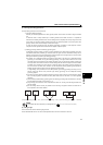
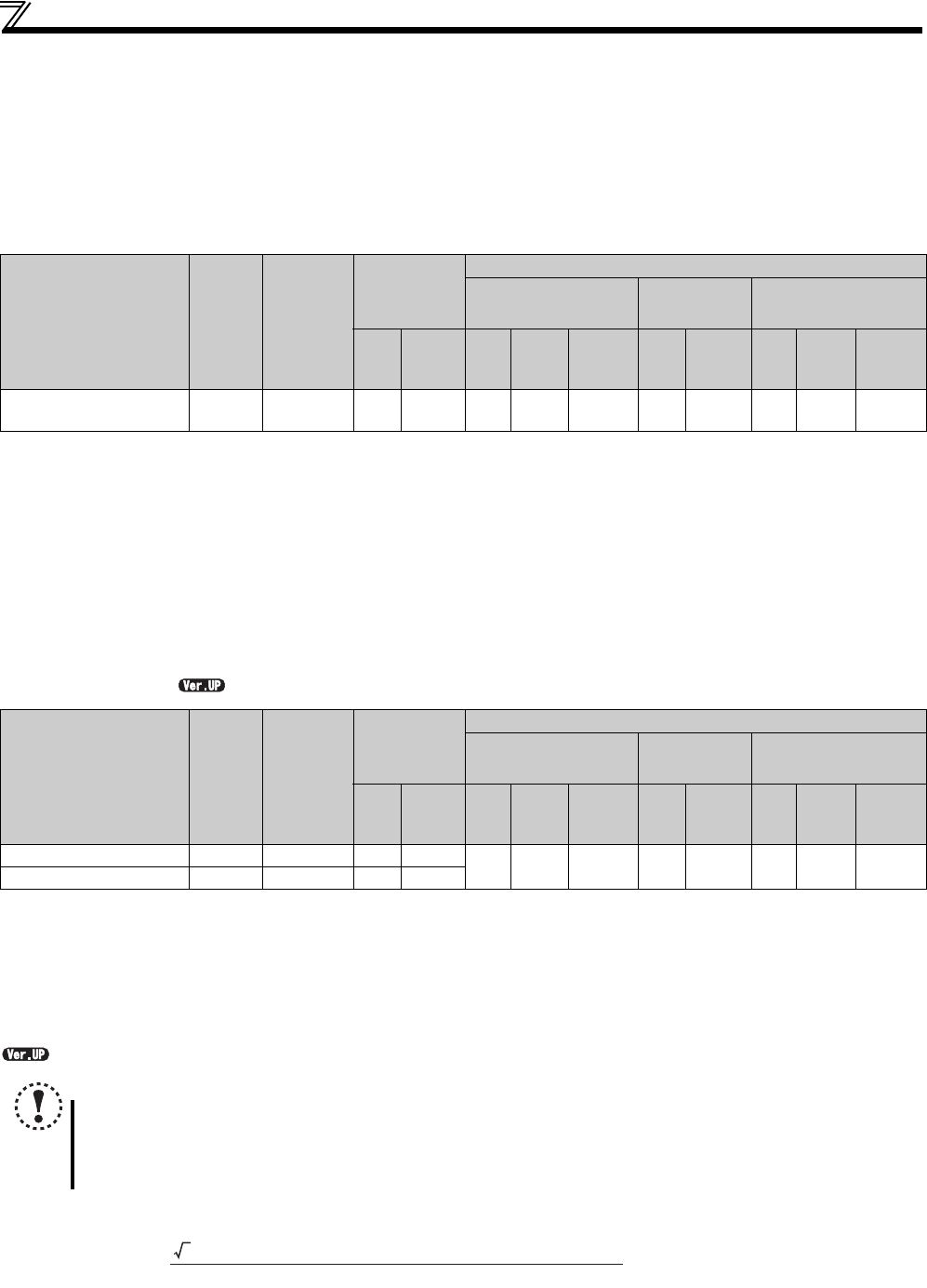
Main circuit terminal specifications
2.2.3 Cables and wiring length
(1) Applicable cable size
Select the recommended cable size to ensure that a voltage drop will be 2% at maximum.
The following table indicates a selection example for the wiring length of 20m.
Three-phase 200V class (when input power supply is 220V)
(1) MM-GKR motor
The cable size is that of the cable (HIV cable (600V class 2 vinyl-insulated cable) etc.) with continuous maximum permissible temperature of 75°C. Assumes
that the surrounding air temperature is 50°C or less and the wiring distance is 20m or less.
The recommended cable size is that of the cable (THHW cable) with continuous maximum permissible temperature of 75°C. Assumes that the surrounding air
temperature is 40°C or less and the wiring distance is 20m or less. (Selection example for use mainly in the United States.)
The recommended cable size is that of the cable (PVC cable) with continuous maximum permissible temperature of 70°C. Assumes that the surrounding air
temperature is 40°C or less and the wiring distance is 20m or less. (Selection example for use mainly in Europe.)
The terminal screw size indicates the terminal size for R/L1, S/L2, T/L3, U, V, W, PR, P/+, N/-, P1 and a screw for earthing (grounding).
The size is 0.75mm
2
(AWG19 or AWG18) when using the motor power supply cable for MM-GKR motor (MR-PWS1CBL
M-A
-
).
When the wiring length of the power supply cable for the motor is 10 m or longer, extend the cable using MR-PWS2CBL03M-A_-L and an HIV wire of 1.25
mm
2
(AWG 16)
For compliance with UL/CSA standards, extend the power supply cable for the motor using MR-PWS2CBL03M-A_-L and an HIV wire of 2 mm
2
(AWG 14).
(2) S-PM geared motor
The cable size is that of the cable (HIV cable (600V class 2 vinyl-insulated cable) etc.) with continuous maximum permissible temperature of 75
°C
.
Assumes that the surrounding air temperature is 50
°C
or less and the wiring distance is 20m or less.
The recommended cable size is that of the cable (THHW cable) with continuous maximum permissible temperature of 75
°C
. Assumes that the surrounding
air temperature is 40
°C
or less and the wiring distance is 20m or less. (Selection example for use mainly in the United States.)
The recommended cable size is that of the cable (PVC cable) with continuous maximum permissible temperature of 70
°C
. Assumes that the surrounding air
temperature is 40
°C
or less and the wiring distance is 20m or less. (Selection example for use mainly in Europe.)
The terminal screw size indicates the terminal size for R/L1, S/L2, T/L3, U, V, W, PR, P/+, N/-, P1 and a screw for earthing (grounding).
.......Specifications differ according to the date assembled. Refer to page 316 to check the SERIAL number.
The line voltage drop can be calculated by the following formula:
Line voltage drop [V]=
Use a larger diameter cable when the wiring distance is long or when it is desired to decrease the voltage drop (torque
reduction) in the low speed range.
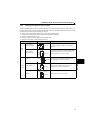
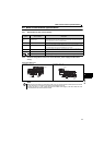
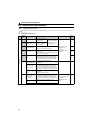
Applicable drive unit
Model
Terminal
Screw
Size
Tightening
Torque
N·m
Crimping
Terminal
Cable Size
HIV Cables, etc.
(mm
2
)
AWG
PVC Cables, etc.
(mm
2
)
R/L1
S/L2
T/L3
U, V, W
R/L1
S/L2
T/L3
U, V, W
Earthing
(grounding)
cable
R/L1
S/L2
T/L3
U, V, W
R/L1
S/L2
T/L3
U, V, W
Earthing
(grounding)
cable
FR-E720EX-0.1K to 0.75K M3.5 1.2 2-3.5 1.25-3.5 2
-
( )
214
-
( )
2.5
-
( )
2.5
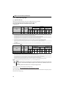
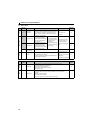
Applicable drive unit
Model
Terminal
Screw
Size
Tightening
Torque
N·m
Crimping
Terminal
Cable Size
HIV Cables, etc.
(mm
2
)
AWG
PVC Cables, etc.
(mm
2
)
R/L1
S/L2
T/L3
U, V, W
R/L1
S/L2
T/L3
U, V, W
Earthing
(grounding)
cable
R/L1
S/L2
T/L3
U, V, W
R/L1
S/L2
T/L3
U, V, W
Earthing
(grounding)
cable
FR-E720EX-0.2K to 0.75K M3.5 1.2 2-3.5 2-3.5
2 2 2 14 14 2.5 2.5 2.5
FR-E720EX-1.5K to 3.7K M4 1.5 2-4 2-4
NOTE
Tighten the terminal screw to the specified torque. A screw that has been tighten too loosely can cause a short circuit
or malfunction. A screw that has been tighten too tightly can cause a short circuit or malfunction due to the unit
breakage.
Use crimping terminals with insulation sleeve to wire the power supply and motor.
3 × wire resistance[mΩ/m] × wiring distance[m] × current[A]
1000