


24
Control circuit specifications
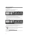
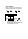
(1) Control circuit common terminals (SD, 5, SE)
Terminals SD, SE and 5 are common terminals for I/O signals. (All common terminals are isolated from each other.) Do not
earth them. Avoid connecting the terminal SD and 5 and the terminal SE and 5.
Terminal SD is a common terminal for the contact input terminals (STF, STR, RH, RM, RL, MRS, RES) and pulse train
output signal (FM). The open collector circuit is isolated from the internal control circuit by photocoupler.
Terminal 5 is a common terminal for the speed setting signals (terminal 2 or 4). It should be protected from external noise
using a shielded or twisted wire.
Terminal SE is a common terminal for the open collector output terminal (RUN, FU). The contact input circuit is isolated
from the internal control circuit by photocoupler.
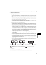
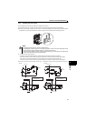
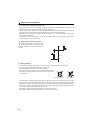
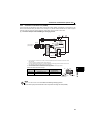
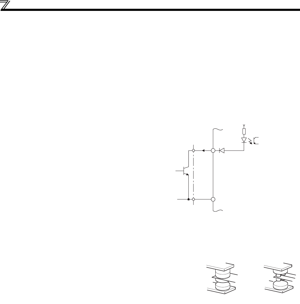
(2) Signal inputs by contactless switches
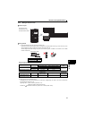
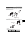
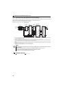
(3) Wiring instructions
It is recommended to use the wires of 0.3mm
2
to 0.75mm
2
gauge for connection to the control circuit terminals.
The maximum wiring length should be 30m (200m for terminal FM).
Do not short terminal PC and SD. Drive unit may be damaged.
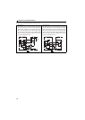
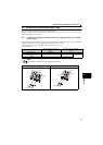
When using contact inputs, use two or more parallel micro-signal contacts or
twin contacts to prevent contact faults since the control circuit input signals
are micro-currents.
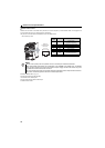
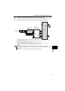
To suppress EMI, use shielded or twisted cables for the control circuit terminals and run them away from the main and
power circuits (including the 200V relay sequence circuit). For the cables connected to the control circuit terminals, connect
their shields to the common terminal of the connected control circuit terminal. When connecting an external power supply to
the terminal PC, however, connect the shield of the power supply cable to the negative side of the external power supply.
Do not directly earth (ground) the shield to the enclosure, etc.
Do not apply a voltage to the contact input terminals (e.g. STF) of the control circuit.
Always apply a voltage to the fault output terminals (A, B, C) via a relay coil, lamp, etc.
The contacted input terminals of the drive unit (STF,
STR, RH, RM, RL, MRS, RES) can be controlled using
a transistor instead of a contacted switch as shown on
the right.
External signal input using transistor
+24V
STF, etc.
SD
Drive unit
Micro signal contacts Twin contacts