


14
Wiring
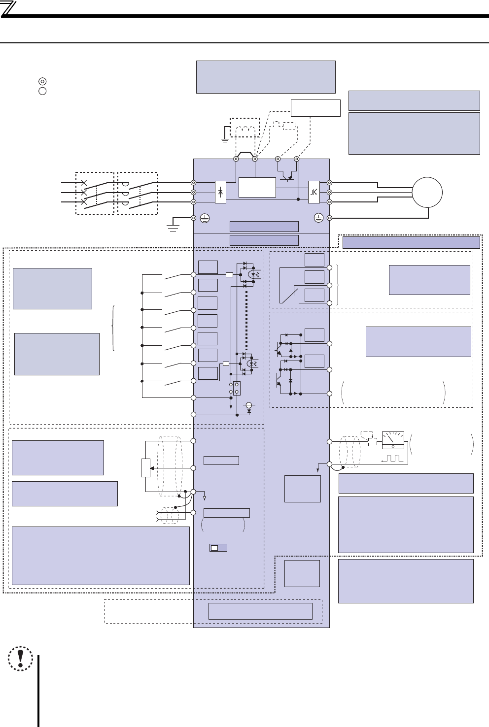
2.1 Wiring
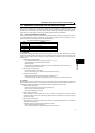
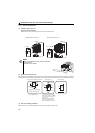
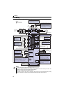
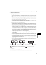
Terminal connection diagram (Speed control)
NOTE
For the terminal connection diagram for the position control, refer to page 90.
To prevent a malfunction caused by noise, separate the signal cables more than 10cm from the power cables. Also
separate the main circuit wire of the input side and the output side.
After wiring, wire offcuts must not be left in the drive unit.
Wire offcuts can cause an alarm, failure or malfunction. Always keep the drive unit clean. When drilling mounting
holes in an enclosure etc., take care not to allow chips and other foreign matter to enter the drive unit.
Earth (Ground)
R/L1
P1 P/+
PR
N/-
S/L2
T/L3
U
V
W
STR
STF
RH
RM
RL
MRS
SD
PC
Relay output
Relay output
(Fault output)
Running
Speed detection
Open collector output
FU
RUN
SE
A
B
C
FM
SD
Indicator
(Speed meter, etc.)
+
-
Moving-coil type
1mA full-scale
Calibration resistor
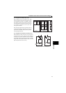
Speed setting signals (Analog)
2
3
1
Speed
setting
potentiometer
1/2W1kΩ
∗4
Connector for
plug-in option connection
Option connector
∗3 Terminal input specifications
can be changed by analog
input specifications switchover
(Pr. 73).
PU
connector
USB
connector
∗8 It is not necessary when calibrating the
indicator from the operation panel.
∗1
∗7
∗6
*2
∗3
∗5
∗8
Terminal functions vary with the
output terminal assignment
(Pr. 190 and Pr. 191)
Terminal functions vary
by Pr. 192 A,B,C
terminal function
SINK
SOURCE
IV
∗5
Brake unit
(Option)
Voltage/current
input switch
Main circuit
Control circuit
Standard control terminal block
R
RES
∗4 It is recommended to use 2W1k
Ω
when the Speed setting signal is
changed frequently.
∗9 Operation and parameter setting can be
done from the parameter unit (FR-PU07)
and the enclosure surface operation panel
(FR-PA07).
(Use the option cable (FR-CB2).)
RS-485 communication can be utilized
from a personal computer and other
∗9
∗10
∗10 A personal computer and a drive unit can
be connected with a USB (Ver1.1) cable.
Parameter setting and monitoring can be
performed by FR Configurator (FR-SW3-
SETUP-W).
Control circuit terminal
Main circuit terminal
Sink logic
∗7 Brake resistor (FR-ABR, MRS, MYS type)
Install a thermal relay to prevent an
overheat and burnout of the brake resistor.
(The brake resistor can not be connected
to the 0.1K and 0.2K.)
∗6 A brake transistor is not built-in to the
0.1K and 0.2K.
∗1 DC reactor (FR-HEL)
When connecting a DC reactor, remove the
jumper across P1 and P/+.
Earth
(Ground)
Three-phase
AC power
supply
MCCB MC
Earth
(Ground)
Jumper
PM
motor
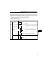
2 0 to 5VDC
10(+5V)
5(Analog common)
(0 to 10VDC)
4 4 to 20mADC
0 to 5VDC
0 to 10VDC
∗5 Terminal input specifications can be changed by analog
input specifications switchover (Pr. 267). Set the
voltage/current input switch in the "V" position to select
voltage input (0 to 5V/0 to10V) and "I" (initial value) to
select current input (4 to 20mA).
To use terminal 4 (initial setting is current input), set "4"
in any of Pr.178 to Pr.184 (input terminal function
selection) to assign the function, and turn ON AU signal.
Terminal 4 input
(Current input)
(+)
(-)
Forward
rotation start
Reverse
rotation start
Middle
speed
High
speed
Low
speed
Output
stop
Reset
Control input signals (No voltage input allowed)
Contact input common
24VDC power supply
(Common for external power supply transistor)
∗2 When using terminals PC
and SD as a 24VDC
power supply, take care
not to short across
terminals PC and SD.
Terminal functions vary
with the input terminal
assignment
(Pr. 178 to Pr. 184)
Multi-speed selection
Open collector output common
Sink/source common
24V
Inrush current
limit circuit