


144
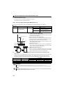
Function assignment of external terminal and control
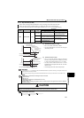
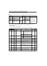
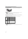
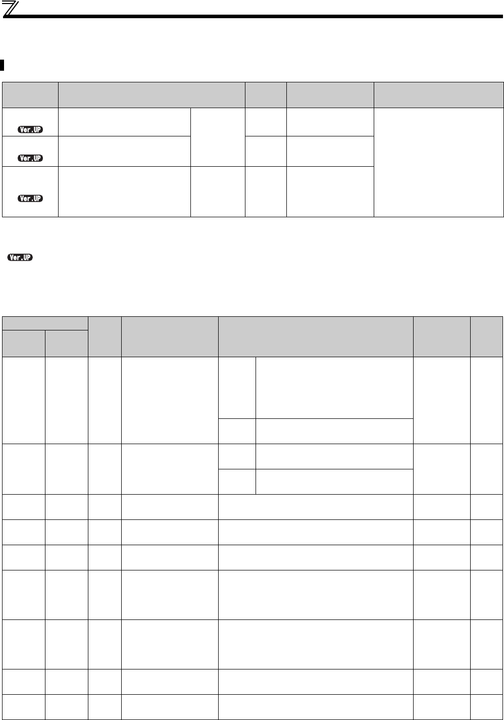
4.12.5 Output terminal function selection (Pr.190 to Pr.192)
(1) Output signal list
You can set the functions of the output terminals.
Refer to the following table and set the parameters: (0 to 99: positive logic, 100 to 199: negative logic)
You can change the functions of the open collector output terminal and relay output terminal.
Parameter
number
Name
Initial
value
Initial signal Setting range
190
RUN terminal function
selection
Open
collector
output
terminal
0
RUN (drive unit
runnning)
0, 1, 3, 4, 7, 8, 11 to 16, 21,
24 to 26, 33, 36, 38, 47, 55, 56,
60, 61, 63, 64, 68, 90, 91, 93,
95, 96, 98, 99, 100, 101, 103,
104, 107, 108, 111 to 116, 121,
124 to 126, 133, 136, 138, 147,
155, 156, 160, 161, 163, 164,
168, 190, 191, 193, 195, 196,
198, 199, 9999
191
FU terminal function
selection
4
FU (rotation speed
detection)
192
A,B,C terminal function
selection
Relay
output
terminal
99 ALM (fault output)
The above parameters can be set when Pr.160 Extended function display selection = "0". (Refer to page 182)
The setting values "93" and "193" are available only in Pr.190 and Pr.191.
The setting values "68" and "168" are valid only when used with FR-E7DS. (For the details, refer to the Instruction Manual of FR-E7DS.)
......Specifications differ according to the date assembled. Refer to page 316 to check the SERIAL number.
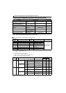
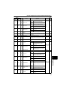
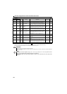
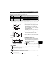
Setting
Signal Function Operation
Related
parameter
Refer
to
page
Positive
logic
Negative
logic
0 100 RUN Drive unit running
Speed
control
Output when the drive unit starts running
upon turning ON of the start signal.
Turned OFF when the drive unit performs
deceleration stop and zero speed control
or servo lock is activated.
147
Position
control
Same operation as that of the RY2 signal
1 101 SU Up to speed
Speed
control
Output when the rotation speed is reached
to the set speed.
Pr.41, Pr.870 149
Position
control
3 103 OL Overload alarm Output while torque limit function is activated.
Pr.22, Pr.48,
Pr.156, Pr.157
111
4 104 FU Rotation speed detection
Output when the rotation speed reaches the speed
set in Pr.42 (Pr.43 for reverse rotation).
Pr.42, Pr.43,
Pr.870
149
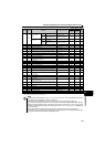
7107RBP
Regenerative brake pre-
alarm
Output when 85% of the regenerative brake duty set
in Pr.70 is reached.
Pr.70 136
8108THP
Electronic thermal O/L
relay pre-alarm
Output when the electronic thermal value reaches
85% of the trip level. (Electronic thermal relay
function protection (E.THT/E.THM) activates, when
the value reached 100%.)
Pr.9 130
11 111 RY Drive unit operation ready
Output when reset process is completed (when the
drive unit can be started by switching the start signal
ON or while it is running) after power-ON of the drive
unit.
147
12 112 Y12 Output current detection
Output when the output current is the Pr.150 setting or
higher for longer than the time set in Pr.151.
Pr.150, Pr.151 150
13 113 Y13 Zero current detection
Output when the output power is the Pr.152 setting or
lower for longer than the time set in Pr.153.
Pr.152, Pr.153 150