


136
Motor brake and stop operation
4.11.3 Selection of a regenerative brake (Pr.30, Pr.70)
The above parameters can be set when Pr.160 Extended function display selection = "0". (Refer to page 182)
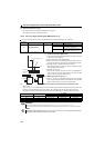
(1) When using the brake resistor (MRS type), brake unit (FR-BU2), power regeneration common
converter (FR-CV), and high power factor converter (FR-HC2).
Set Pr.30 to "0" (initial value). The Pr.70 setting is made invalid.
At this time, the regenerative brake duty is 3%.
Assign the drive unit operation enable signal (X10) to the contact input terminal. To make protective coordination with the
FR-HC2 and FR-CV, use the drive unit operation enable signal to shut off the drive unit output.
Input the RDY signal of the FR-HC2 (RDYB signal of the FR-CV).
For the terminal used for X10 signal input, assign its function by setting "10" (X10) to any of Pr.178 to Pr.184.
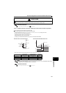
(2) When using the high-duty brake resistor (FR-ABR) (0.4K or higher)
Set "1" in Pr.30.
Set "10%" in Pr.70.
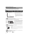
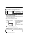
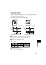
(3) Regenerative brake duty alarm output and alarm signal (RBP signal)
When making frequent starts/stops, use the optional brake resistor (MRS type), high-duty brake resistor (FR-ABR)
and brake unit (FR-BU2) to increase the regenerative brake duty.
Use a power regeneration common converter (FR-CV) for continuous operation in regeneration status.
Use the high power factor converter (FR-HC2) to reduce harmonics, improve the power factor, or continuously use
the regenerative status.
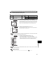
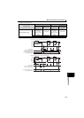
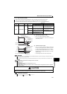
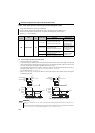
Parameter
number
Name
Initial
value
Setting
range
Description
30
Regenerative function
selection
0
0
Drive unit without regenerative function
Brake resistor (MRS type)
Brake unit (FR-BU2)
Power regeneration common converter (FR-CV)
High power factor converter (FR-HC2)
1 High-duty brake resistor (FR-ABR)
70 Special regenerative brake duty
0% 0 to 30% Brake duty when using the high-duty brake resistor (FR-ABR)
100%: regenerative overvoltage protection operation value
[RB] appears on the operation panel and an alarm signal
(RBP) is output when 85% of the regenerative brake duty
set in Pr.70 is reached. If the regenerative brake duty
reaches 100% of the Pr.70 setting, a regenerative
overvoltage (E.OV1 to E.OV3) occurs.
Note that [RB] is not displayed when Pr.30 = "0".
The drive unit does not trip even when the alarm (RBP)
signal is output.
For the terminal used for the RBP signal output, assign
the function by setting "7 (positive logic) or 107 (negative
logic)" in any of Pr.190 to Pr.192 (output terminal function
selection).
REMARKS
The MRS signal can also be used instead of the X10 signal. (Refer to page 140)
Refer to page 27 to 31 for connecting the brake resistor (MRS type), high-duty brake resistor (FR-ABR), brake unit (FR-BU2),
high power factor converter (FR-HC2), and power regeneration common converter (FR-CV).
NOTE
When terminal assignment is changed using Pr.178 to Pr.184 (input terminal function selection) and Pr.190 to Pr.192 (output
terminal function selection), the other functions may be affected. Set parameters after confirming the function of each
terminal. (Refer to page 138)
WARNING
The value set in Pr.70 must not exceed the setting of the brake resistor used.
Otherwise, the resistor can overheat.
Parameters referred to
Pr.178 to Pr.184 (input terminal function selection) Refer to page 138
Pr.190 to Pr.192 (output terminal function selection) Refer to page 144
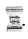
Ratio of the brake
duty to the Pr. 70
setting (%)
Regenerative brake
pre-alarm (RBP)
Time
ONONOFF
100
85