


45
Failsafe of the system which uses the drive unit
3
PRECAUTIONS FOR USE OF THE DRIVE UNIT
3.5 Failsafe of the system which uses the drive unit
When a fault occurs, the drive unit trips and outputs a fault signal. However, a fault signal may not be output at a drive unit
fault occurrence when the detection circuit or output circuit fails, etc. Although Mitsubishi assures best quality products,
provide an interlock which uses drive unit status output signals to prevent accidents such as damage to machine when the
drive unit fails for some reason. At the same time, consider the system configuration where failsafe from outside the drive unit,
without using the drive unit, is enabled in case the drive unit fails.
(1) Interlock method which uses the drive unit status output signals
By combining the drive unit status output signals to provide an interlock as shown below, a drive unit alarm can be
detected.
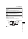
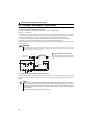
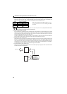
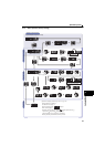
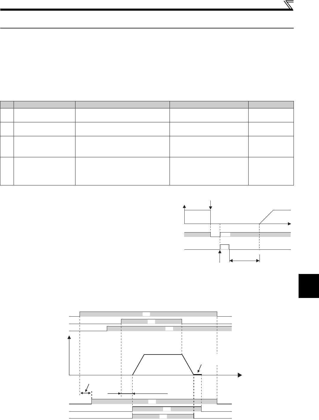
1)Check by the output of the drive unit fault signal
When the drive unit's protective function activates and the
drive unit trips, the fault output signal (ALM signal) is output.
(ALM signal is assigned to terminal ABC in the initial setting).
With this signal, you can check if the drive unit is operating
properly.
In addition, negative logic can be set (ON when the drive unit
is normal, OFF when the fault occurs).
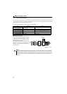
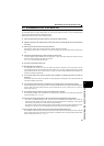
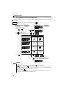
2)Checking the drive unit operating status by the drive unit operation ready completion signal
Operation ready signal (RY signal) is output when the drive unit power is on and the drive unit becomes operative.
Check if the RY signal is output after power-ON the drive unit.
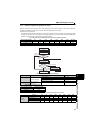
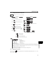
3)Checking the drive unit operating status by the start signal input to the drive unit and drive unit running signal.
The drive unit running signal (RUN signal) is output when the drive unit is running (RUN signal is assigned to terminal
RUN in the initial setting).
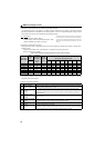
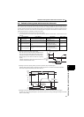
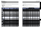
No. Interlock Method Check Method Used Signals Refer to Page
1)
Drive unit protective
function operation
Operation check of an alarm contact
Circuit error detection by negative logic
Fault output signal
(ALM signal)
148
2) Drive unit running status Operation ready signal check
Operation ready signal
(RY signal)
147
3) Drive unit running status
Logic check of the start signal and running
signal
Start signal
(STF signal, STR signal)
Running signal (RUN signal)
142, 147
4) Drive unit running status
Logic check of the start signal and output
current
Start signal
(STF signal, STR signal)
Output current detection signal
(Y12 signal)
142, 150
ON
OFF
Reset ON
Rotation speed
ALM
(when output
at NC contact)
RES
Drive unit fault occurrence
(trip)
Time
OFF
ON
Reset processing
(about 1s)
Power
supply
STF
RH
Zero speed
control activated
Time
Rotation speed
Reset
processing
RY
RUN
RY2
ON
ON
ON
ON
ON
ON
Initial magnetic
pole detection
(approx. 100 ms)
(r/min)