


46
Failsafe of the system which uses the drive unit
Check if RUN signal is output when inputting the start signal to the drive unit (forward signal is STF signal and reverse
signal is STR signal). For logic check, note that RUN signal is output for the period from the drive unit decelerates until
output to the motor is stopped, configure a sequence considering the drive unit deceleration time
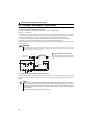
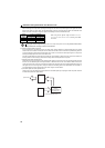
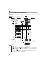
(2) Backup method outside the drive unit
Even if the interlock is provided by the drive unit status signal, enough failsafe is not ensured depending on the failure
status of the drive unit itself. For example, when the drive unit CPU fails, even if the interlock is provided using the drive
unit fault output signal, start signal and RUN signal output, there is a case where a fault output signal is not output and
RUN signal is kept output even if a drive unit fault occurs.
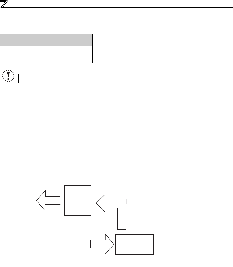
Provide a speed detector to detect the motor speed and current detector to detect the motor current and consider the
backup system such as checking up as below according to the level of importance of the system.
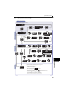
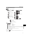
1)Start signal and actual operation check
Check the motor running and motor current while the start signal is input to the drive unit by comparing the start signal to
the drive unit and detected speed of the speed detector or detected current of the current detector. Note that the motor
current runs as the motor is running for the period until the motor stops since the drive unit starts decelerating even if the
start signal turns off. For the logic check, configure a sequence considering the drive unit deceleration time. In addition, it
is recommended to check the three-phase current when using the current detector.
2)Command speed and actual operation check
Check if there is no gap between the actual speed and commanded speed by comparing the drive unit speed command
and detected speed of the speed detector.
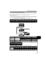
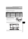
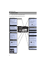
Output
signal
Pr.190 to Pr.192 Setting
When using various signals, assign functions to Pr.190 to
Pr.192 (output terminal function selection) referring to the table
on the left.
Positive logic Negative logic
ALM 99 199
RY 11 111
RUN 0 100
NOTE
Changing the terminal assignment using Pr.190 to Pr.192 (output terminal function selection) may affect the other functions.
Set parameters after confirming the function of each terminal.
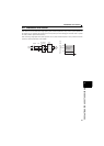
Drive unit
Controller
System failure
To the alarm detection sensor
Sensor
(speed, temperature,
air volume, etc.)