


159
Monitor display and monitor output signal
4
PARAMETERS
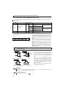
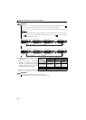
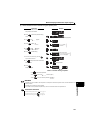
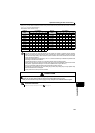
(3) Operation panel I/O terminal monitor (Pr.52)
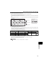
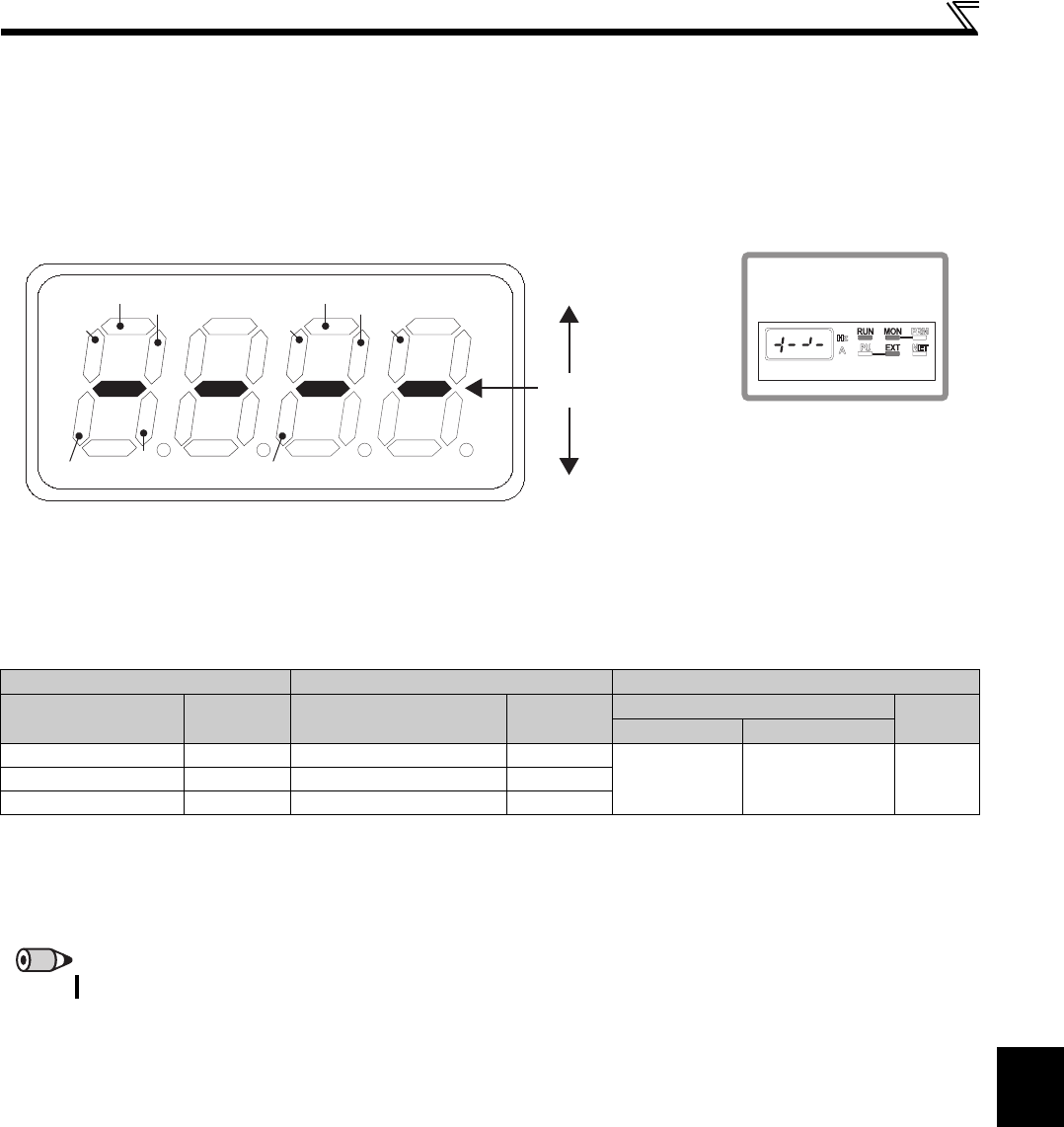
When Pr.52 is set to "55", the I/O terminal status can be monitored on the operation panel.
The I/O terminal monitor is displayed on the third monitor.
The LED is ON when the terminal is ON, and the LED is OFF when the terminal is OFF. The center line of LED is always
ON.
On the unit I/O terminal monitor (Pr.52 = "55"), the upper LEDs denote the input terminal status and the lower the output
terminal status.
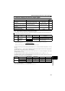
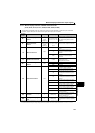
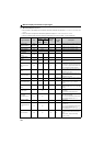
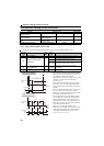
(4) Cumulative power monitor and clear (Pr.170)
On the cumulative power monitor (Pr.52 = "25"), the output power monitor value is added up and is updated in 100ms
increments. (The values are saved in EEPROM every hour.)
The operation panel, parameter unit (FR-PU07) and communication (RS-485 communication, communication option)
display increments and display ranges are as indicated below.
Writing "0" to Pr.170 clears the cumulative power monitor.
Operation Panel Parameter Unit Communication
Range Unit Range Unit
Range
Unit
Pr.170 = 10 Pr.170 = 9999
0 to 99.99kWh 0.01kWh 0 to 999.99kWh 0.01kWh
0 to 9999kWh
0 to 65535kWh
(initial value)
1kWh100.0 to 999.9kWh 0.1kWh 1000.0 to 9999.9kWh 0.1kWh
1000 to 9999kWh 1kWh 10000 to 99999kWh 1kWh
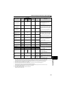
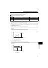
Power is measured in the range 0 to 9999.99kWh, and displayed in 4 digits.
When the monitor value exceeds "99.99", a carry occurs, e.g. "100.0", so the value is displayed in 0.1kWh increments.
Power is measured in the range 0 to 99999.99kWh, and displayed in 5 digits.
When the monitor value exceeds "999.99", a carry occurs, e.g. "1000.0", so the value is displayed in 0.1kWh increments.
REMARKS
If "0" is written to Pr.170 and Pr.170 is read again, "9999" or "10" is displayed.
RM
RL
RH
MRS STR
RES
RUN
FUABC
STF
Center line is always ON
Input terminal
- Display example -
When signals STF, RH and
RUN are ON
Output terminal
Hz
A
V