


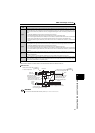


40
EMC and leakage currents
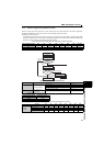
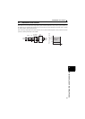
1) Calculation of equivalent capacity (P0) of harmonic generating equipment
The "equivalent capacity" is the capacity of a 6-pulse converter converted from the capacity of consumer's harmonic
generating equipment and is calculated with the following equation. If the sum of equivalent capacities is higher than the
limit in Table 3, harmonics must be calculated with the following procedure:
2) Calculation of outgoing harmonic current
Outgoing harmonic current = fundamental wave current (value converted from received power voltage) operation ratio
harmonic content
Operation ratio: Operation ratio = actual load factor operation time ratio during 30 minutes
Harmonic content: Found in Table 4.
3) Application of the guideline for specific consumers
If the outgoing harmonic current is higher than the maximum value per 1kW contract power contract power, a harmonic
suppression technique is required.
4) Harmonic suppression techniques
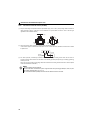
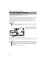
P0 =
(KiPi) [kVA]
Rated capacity: Determined by the capacity of the applied motor
and found in Table 5. It should be noted that the rated capacity
used here is used to calculate generated harmonic amount and is
different from the power supply capacity required for actual drive
unit drive.
Ki: Conversion factor (refer to Table 2)
Pi: Rated capacity of harmonic generating equipment. [kVA]
i: Number indicating the conversion circuit type
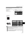
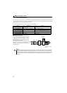
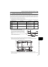
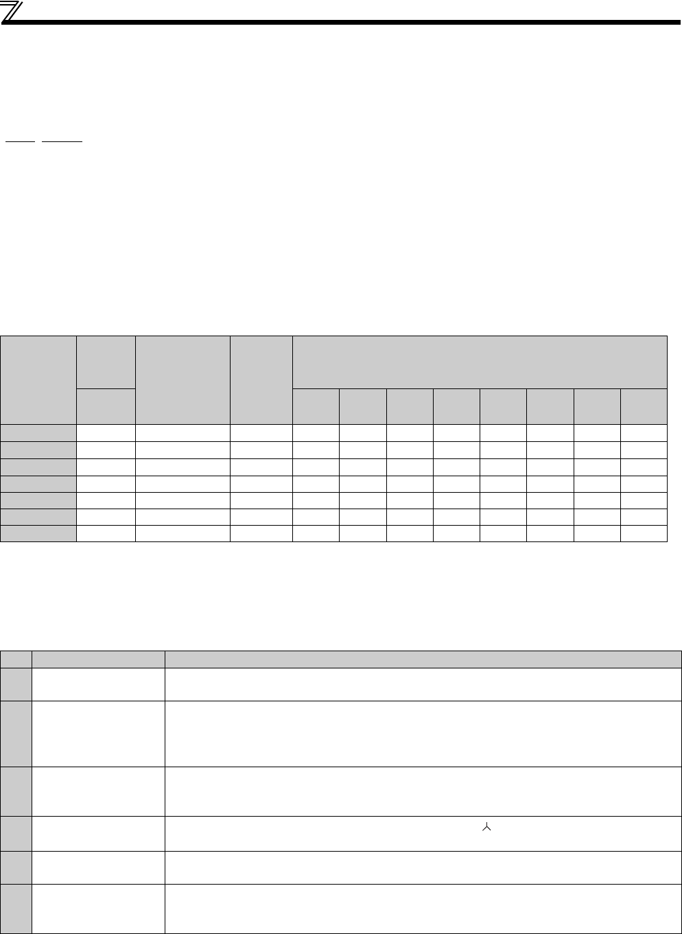
Table 5 Rated Capacities and Outgoing Harmonic Currents for Drive unit Drive
Applicable
Motor (kW)
Rated
Current
[A]
Fundamental
Wave Current
Converted
from 6.6kV
(mA)
Rated
Capacity
(kVA)
Outgoing Harmonic Current Converted from 6.6kV(mA)
(No reactor, 100% operation ratio)
200V 5th 7th 11th 13th 17th 19th 23rd 25th
0.1
0.61 18 0.22 11.7 7.38 1.53 1.386 0.774 0.558 0.468 0.324
0.2
0.98 30 0.35 19.5 12.3 2.55 2.31 1.29 0.93 0.78 0.54
0.4
1.61 49 0.57 31.85 20.09 4.165 3.773 2.107 1.519 1.274 0.882
0.75 2.74 83 0.97 53.95 34.03 7.055 6.391 3.569 2.573 2.158 1.494
1.5 5.50 167 1.95 108.6 68.47 14.20 12.86 7.181 5.177 4.342 3.006
2.2 7.93 240 2.81 156.0 98.40 20.40 18.48 10.32 7.440 6.240 4.320
3.7 13.0 394 4.61 257.1 161.5 33.49 30.34 16.94 12.21 10.24 7.092
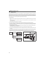
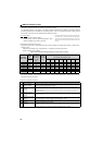
No. Item Description
1
Reactor installation
(FR-HAL, FR-HEL)
Install an AC reactor (FR-HAL) on the AC side of the drive unit or a DC reactor (FR-HEL) on its DC side
or both to suppress outgoing harmonic currents.
2
High power factor
converter
(FR-HC2)
This converter trims the current waveform to be a sine waveform by switching in the rectifier circuit
(converter module) with transistors. Doing so suppresses the generated harmonic amount significantly.
Connect it to the DC area of a drive unit. The high power factor converter (FR-HC2) is used with the
standard accessory.
3
Installation of power
factor improving
capacitor
When used with a series reactor, the power factor improving capacitor has an effect of absorbing
harmonic currents.
4
Transformer multi-phase
operation
Use two transformers with a phase angle difference of 30° as in -, - combination to provide an
effect corresponding to 12 pulses, reducing low-degree harmonic currents.
5
Passive filter
(AC filter)
A capacitor and a reactor are used together to reduce impedances at specific frequencies, producing a
great effect of absorbing harmonic currents.
6 Active filter
This filter detects the current of a circuit generating a harmonic current and generates a harmonic current
equivalent to a difference between that current and a fundamental wave current to suppress a harmonic
current at a detection point, providing a great effect of absorbing harmonic currents.