


233
Communication operation and setting
4
PARAMETERS
Faults history
Fault code list
Model information monitor
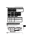
(7) Pr.343 Communication error count
You can check the cumulative number of communication errors.
(8) Output terminal LF "alarm output (communication error warnings)"
During a communication error, the alarm signal (LF signal) is output by open collector output. Assign the used terminal
using any of Pr.190 to Pr.192 (output terminal function selection).
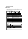
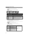
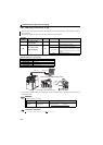
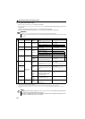
Register Definition Read/Write Remarks
40501 Fault history 1 Read/Write
Being 2 bytes in length, the data is stored as "H00".
Refer to the lowest 1 byte for the error code.
Performing write using the register 40501 batch-clears
the faults history.
Set any value as data.
40502 Fault history 2 Read
40503 Fault history 3 Read
40504 Fault history 4 Read
40505 Fault history 5 Read
40506 Fault history 6 Read
40507 Fault history 7 Read
40508 Fault history 8 Read
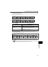
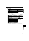
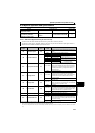
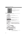
Register Definition Read/Write Remarks
44001 to 44010
Drive unit
model
Read
Reading drive unit model in ASCII code.
"H20" (blank code) is set for blank area
Example of FR-E720EX
H46, H52, H2D, H45, H37, H32, H30, H45, H58, H20 ......H20
44011 to 44013 Capacity Read
Reading drive unit capacity in ASCII code.
Data is read in increments of 0.1kW, and rounds down to
0.01kW increments
"H20" (blank code) is set for blank area
Example
0.75K................" 7" (H20, H20, H20, H20, H20, H37)
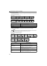
Parameter Setting Range Minimum Setting Range Initial Value
343 (Reading only) 1 0
NOTE
The number of communication errors is temporarily stored into the RAM. As it is not stored into the EEPROM
performing a power supply reset or drive unit reset clears the value to 0.
NOTE
The LF signal can be assigned to the output terminal using any of Pr.190 to Pr.192. Changing the terminal assignment
may affect the other functions. Set parameters after confirming the function of each terminal.
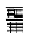
Refer to page 267 for details of fault description.
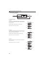
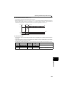
Data Definition
H00
No fault
present
H10 E.OC1
H11 E.OC2
H12 E.OC3
H20 E.OV1
H21 E.OV2
H22 E.OV3
H30 E.THT
H31 E.THM
H40 E.FIN
H52 E.ILF
H60 E.OLT
H61 E.SOT
H70 E.BE
H80 E.GF
H81 E.LF
H90 E.OHT
HA0 E.OPT
HA1 E.OP1
Data Definition
HB0 E.PE
HB1 E.PUE
HB2 E.RET
HB3 E.PE2
HC0 E.CPU
HC5 E.IOH
HC7 E.AIE
HC8 E.USB
HC9 E.SAF
HD0 E.OS
Data Definition
HD1 E.OSD
HD3 E.OD
HDD E.OA
HF1 E.1
HF5 E.5
HF6 E.6
HF7 E.7
HFD E.13
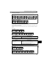
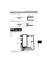
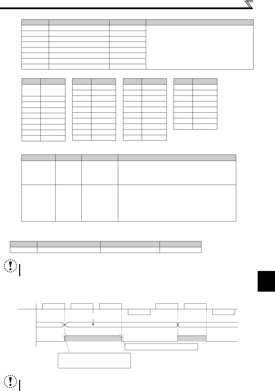
Data Definition
Alarm data
Reply data
Master
Slave
Communication
Error count
(Pr.343)
0
LF signal
Normal dataAlarm data Alarm data Normal data
Reply data
12
OFF
ON
OFF OFF
ON
Not increased
Communication error count is increased
in synchronization with leading edge
of LF signal
Turns OFF when normal data is received
Alarm data: Data resulting in communication error.