


93
4
PARAMETERS
Position control
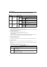
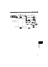
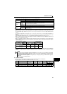
(3) Model adaptive speed control (Pr.446, Pr.877 = "2")
The model speed of the motor is calculated, and the feedback is applied to the position controller on the model side.
Also, this model position is set as the command of the actual position controller.
The Pr.446 setting is used for the gain of the model position controller and the Pr.422 setting is used for the actual position
control gain.
The inertia ratio of Pr.880 is used when the model calculates the motor speed or the speed controller calculates the
torque current command value.
The torque current command of the speed controller and calculation of the motor speed on the model side are added to
the output of the actual speed controller, and set as the input of the iq current control.
Pr.828 is used for the speed control on the model side (P control), and first gain Pr.820 is used for the actual speed
controller.
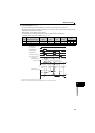
(4) Speed control D gain (Pr.698)
Adjusting Pr.698 Speed control D gain suppresses unstable movement (vibration). This is useful when the machine has
difficulty in stopping at the target position (vibrated around the target position) during positioning operation under position
control.
Setting Pr.698 = 100% sets the corner frequency of f = 10rad/s (f = 10rad/sPr.698
% )and reduces the response
level to the frequency lower than that. Position deviation, however, increases as a higher value is set in Pr.698.
(5) Excessive error level (Pr.427)
If the number of droop pulses [after the electronic gear] exceeds the Pr.427 Excessive level error setting, an error (E.OD) is
displayed and the operation is stopped. If a small value is set in Pr.422 Position control gain, the droop pulse is increased.
Thus, set a large value in Pr.427.
To detect the excessive position error at an overload early, set a small value.
Number of droop pulses [after electronic gear] = Position command [after electronic gear] - Current position [after
electronic gear]
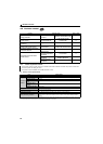
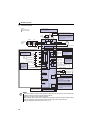
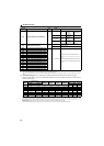
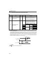
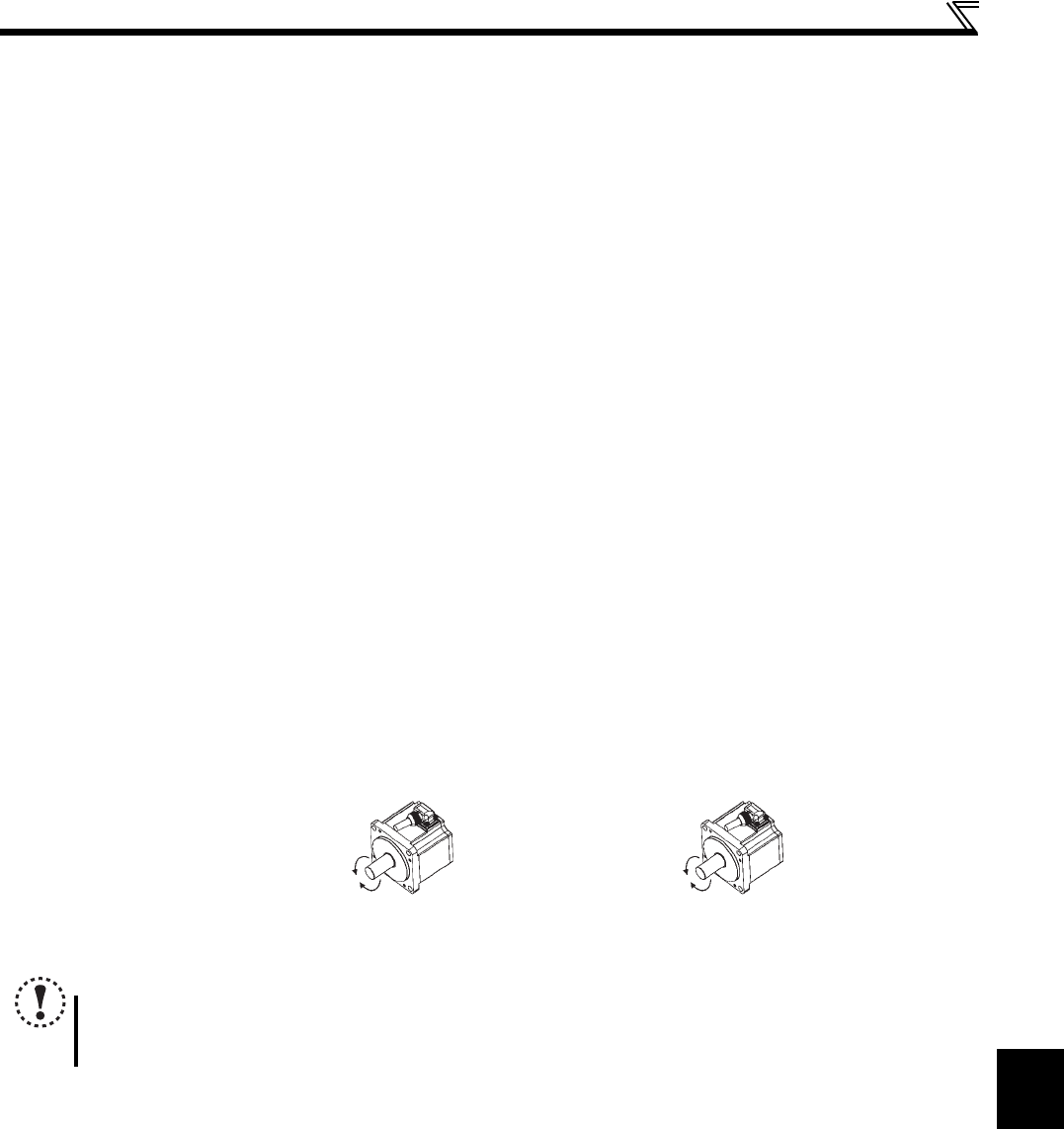
(6) Motor rotation direction and position pulse accumulation (Pr.463)
When Pr.463 Position control rotation direction selection = "0", the position pulse (current position) increases in the CCW
rotation seen from the motor shaft, and decreases in the CW rotation seen from the motor shaft.
When Pr.463 Position control rotation direction selection = "1", the position pulse (current position) decreases in the CCW
rotation seen from the motor shaft, and increases in the CW rotation seen from the motor shaft.
NOTE
Pr.463 can be written while the operation is stopped (while the start signal of the drive unit is OFF and the output is
shut off), and the setting is applied immediately.
Setting cannot be written during operation.
CCW: The position pulse
(current position) increases.
CCW: The position pulse
(current position) decreases.
CW: The position pulse
(current position) increases.
CW: The position pulse
(current position) decreases.
For Pr.463 = "0" For Pr.463 = "1"