


157
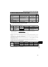
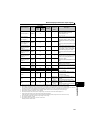
Monitor display and monitor output signal
4
PARAMETERS
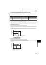
When "102 or higher" is set in Pr.144 Speed setting switchover, the speed display is enabled. For "2 to 10", the frequency display is enabled.
Speed setting to output terminal status on the PU main monitor are selected by "other monitor selection" of the parameter unit (FR-PU07).
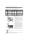
The cumulative energization time and actual operation time are accumulated from 0 to 65535 hours, then cleared, and accumulated again from 0. When the
operation panel is used, the time is displayed up to 65.53 (65530h) in the indication of 1h = 0.001, and thereafter, it is added up from 0.
Actual operation time is not accumulated when the cumulative operation time is less than 1h until turning OFF of the power supply.
When using the parameter unit (FR-PU07), "kW" is displayed.
Since the panel display of the operation panel is 4 digits in length, the monitor value of more than "9999" is displayed "----".
Larger thermal value between the motor thermal and transistor thermal is displayed.
A value other than 0% is displayed if the surrounding air temperature (heatsink temperature) is high even when the drive unit is at a stop.
For the parameter unit (FR-PU07), the display is upper 5 digits or lower 5 digits.
The unit used for the display is 10000.
The monitored values are retained even if an drive unit fault occurs.
Resetting will clear the retained values.
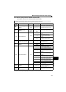
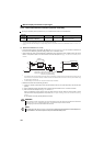
Cumulative power
0.01kWh
25 —
Adds up and displays the power amount
based on the output power monitor.
Can be cleared by Pr.170.
(Refer to page 159)
Position command
[before electronic gear]
(lower 4 digits)
126 —
Position command [before electronic gear]
= position command [before electronic
gear] (upper 4 digits)
10000 + position
command [before electronic gear] (lower 4
digits)
Without a sign (always displayed as a plus
value.)
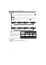
Position command
[before electronic gear]
(upper 4 digits)
10000 27 —
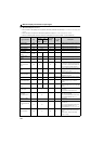
Current position [before
electronic gear] (lower
4 digits)
128 —
Current position [before electronic gear] =
current position [before electronic gear]
(upper 4 digits)
10000 + current position
[before electronic gear] (lower 4 digits)
Without a sign (always displayed as a plus
value.)
Current position [before
electronic gear] (upper
4 digits)
10000 29 —
Droop pulse [after
electronic gear] (lower
4 digits)
130 —
Droop pulse [after electronic gear] = droop
pulse [after electronic gear] (upper 4 digits)
10000 + droop pulse [after electronic
gear] (lower 4 digits)
Without a sign (always displayed as a plus
value.)
Droop pulse [after
electronic gear] (upper
4 digits)
10000 31 —
Ideal speed command
1r/min
(0.01Hz)
36 36 Pr.55
Displays an ideal speed command for
creating a position command.
Speed command
1r/min
(0.01Hz)
37 37 Pr.55
Displays the speed command after position
loop.
PID set point 0.1% 52 52 100% Displays the set point, measured value and
deviation during PID controlPID (Refer to
page 239 for details)
PID measured value 0.1% 53 53 100%
PID deviation 0.1% 54 —
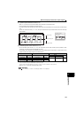
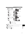
Drive unit I/O terminal
monitor
—55 —
Displays the ON/OFF status of the drive
unit input terminal and output terminal on
the operation panel
(Refer to page 159 for details)
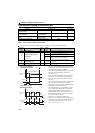
Motor thermal load
factor
0.1% 61 61
Thermal relay
operation level
(100%)
Motor thermal heat cumulative value is
displayed.
(Motor overload trip (E.THM) at 100%)
Drive unit thermal load
factor
0.1% 62 62
Thermal relay
operation level
(100%)
Transistor thermal heat cumulative value is
displayed.
(Drive unit overload trip (E.THT) at 100%)
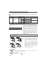
Types of Monitor Unit
Pr.52 Setting
Pr.54 (FM)
Setting
Terminal FM
Full Scale
Value
Description
Operation
Panel
LED
PU
Main
Monitor