


146
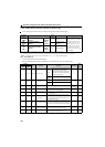
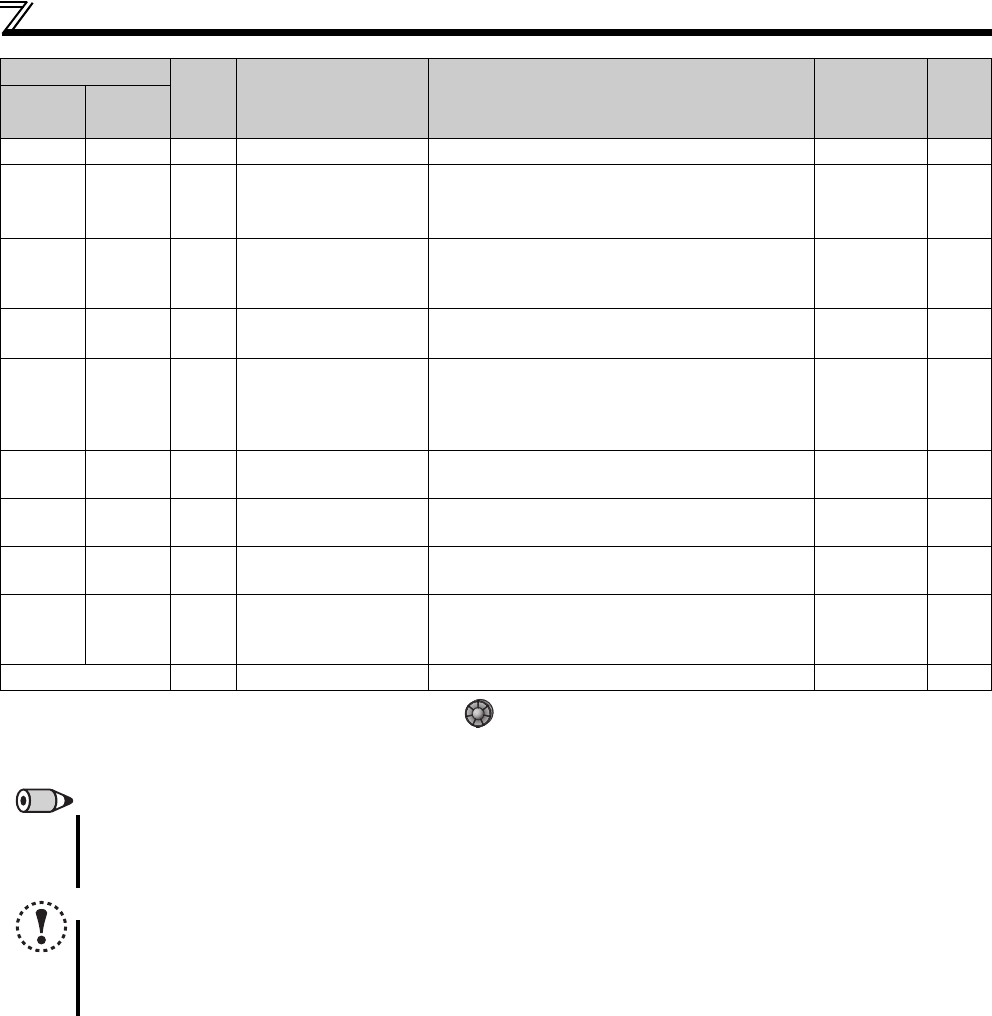
Function assignment of external terminal and control
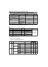
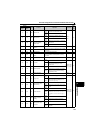
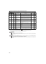
64 164 Y64 During retry Output during retry processing. Pr.65 to Pr.69 164
68 168 EV
24V external power
supply operation
The signal is output while the main circuit power
supply is off and the 24V power is supplied externally.
This signal is available when FR-E7DS is mounted.
90 190 Y90 Life alarm
Output when any of the control circuit capacitor, main
circuit capacitor and inrush current limit circuit or the
cooling fan approaches the end of its service life.
Pr.255 to
Pr.259
245
91 191 Y91
Fault output 3
(power-off signal)
Output when a fault occurs due to the internal circuit
failure of the drive unit wiring mistake.
148
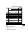
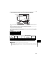
93 193 Y93
Current average value
monitor signal
Average current value and maintenance timer value
are output as pulses.
The signal can not be set in Pr.192 A,B,C terminal
function selection.
Pr.555 to
Pr.557
249
95 195 Y95 Maintenance timer signal
Output when Pr.503 rises to or above the Pr.504
setting.
Pr.503, Pr.504 248
96 196 REM Remote output
Output to the terminal when a value is set to the
parameter.
Pr.495, Pr.496 152
98 198 LF Alarm output
Output when an alarm (communication error warning)
occurs.
Pr.121 204
99 199 ALM Fault output
Output when the drive unit's protective function is
activated to stop the output (at fault occurrence).
The signal output is stopped when the fault is reset.
148
9999 No function
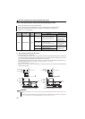
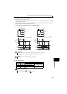
Note that when the speed setting is varied using an analog signal or of the operation panel, the output of the SU (up to speed) signal may alternate
ON and OFF depending on that varying speed and the timing of the varying speed due to acceleration/deceleration time setting.
(The output will not alternate ON and OFF when the acceleration/deceleration time setting is "0s".)
REMARKS
The same function may be set to more than one terminal.
When the function is executed, the terminal conducts at the setting of any of "0 to 99", and does not conduct at the setting of
any of "100 to 199".
NOTE
Changing the terminal assignment using Pr.190 to Pr.192 (output terminal function selection) may affect the other
functions. Set parameters after confirming the function of each terminal.
Do not assign signals which repeat frequent ON/OFF to terminal A, B, C. Otherwise, the life of the relay contact
decreases.
Setting
Signal Function Operation
Related
parameter
Refer
to
page
Positive
logic
Negative
logic