


273
5
TROUBLESHOOTING
Causes and corrective actions
Resetting the drive unit initializes the internal thermal integrated data of the electronic thermal relay function.
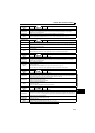
Operation panel
indication
E.OV1
FR-PU07 OV During Acc
Name
Regenerative overvoltage trip during acceleration
Description
If regenerative energy causes the drive unit's internal main circuit DC voltage to reach or exceed the specified value,
the protective circuit is activated and the drive unit trips. The circuit may also be activated by a surge voltage
produced in the power supply system.
Check point
Check for too slow acceleration. (e.g. during downward acceleration in vertical lift load)
Corrective
action
Decrease the acceleration time.
Check that regeneration avoidance function (Pr.882, Pr.883, Pr.885, Pr.886) is used. (Refer to page 242)
Operation panel
indication
E.OV2
FR-PU07 Stedy Spd OV
Name
Regenerative overvoltage trip during constant speed
Description
If regenerative energy causes the drive unit's internal main circuit DC voltage to reach or exceed the specified value,
the protective circuit is activated to stop the drive unit output. The circuit may also be activated by a surge voltage
produced in the power supply system.
Check point
Check for sudden load change.
Corrective
action
Keep load stable.
Check that regeneration avoidance function (Pr.882, Pr.883, Pr.885, Pr.886) is used. (Refer to page 242)
Use the brake resistor, brake unit or power regeneration common converter (FR-CV) as required.
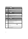
Operation panel
indication
E.OV3
FR-PU07 OV During Dec
Name
Regenerative overvoltage trip during deceleration or stop
Description
If regenerative energy causes the drive unit's internal main circuit DC voltage to reach or exceed the specified value,
the protective circuit is activated to stop the drive unit output. The circuit may also be activated by a surge voltage
produced in the power supply system.
Check point
Check for sudden speed reduction.
Corrective
action
Increase the deceleration time. (Set the deceleration time which matches the moment of inertia of the load)
Longer the brake cycle.
Use regeneration avoidance function (Pr.882, Pr.883, Pr.885, Pr.886). (Refer to page 242)
Use the brake resistor, brake unit or power regeneration common converter (FR-CV) as required.
Operation panel
indication
E.THT
FR-PU07 Inv. Overload
Name
Drive unit overload trip (electronic thermal relay function)
Description
If the temperature of the output transistor element exceeds the protection level under the condition that a current not
less than the rated drive unit current flows and overcurrent trip does not occur (230% or less), the electronic thermal
relay activates to stop the drive unit output. (Overload capacity 150% 60s, 200% 3s)
Check point
Check that acceleration/deceleration time is not too short.
Check the motor for use under overload.
Check for too high surrounding air temperature.
Corrective
action
Increase acceleration/deceleration time.
Reduce the load weight.
Set the surrounding air temperature to within the specifications.
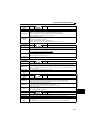
Operation panel
indication
E.THM
FR-PU07 Motor Ovrload
Name
Motor overload trip (electronic thermal relay function)
Description
The electronic thermal relay function in the drive unit detects motor overheat due to overload or reduced cooling
capability during low-speed operation and pre-alarm (TH display) is output when the integrated value reaches 85% of
the Pr.9 Electronic thermal O/L relay setting and the protection circuit is activated to stop the drive unit output when the
integrated value reaches the specified value.
Check point
Check the motor for use under overload.
Check that torque limit operation setting is correct.
Corrective
action
Reduce the load weight.
Check that torque limit operation setting is correct. (Refer to page 111)