


152
Function assignment of external terminal and control
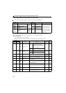
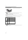
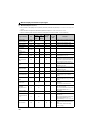
4.12.8 Remote output selection (REM signal, Pr.495, Pr.496)
You can utilize the ON/OFF of the drive unit's output signals instead of the remote output terminal of the programmable
logic controller.
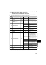
Parameter
number
Name
Initial
value
Setting
range
Description
495
Remote output
selection
0
0
Remote output data clear at
powering OFF Remote output data is cleared
during a drive unit reset
1
Remote output data retention at
powering OFF
10
Remote output data clear at
powering OFF Remote output data is retained
during a drive unit reset
11
Remote output data retention at
powering OFF
496 Remote output data 1
0 0 to 4095 Refer to the following diagram.
The above parameters can be set when Pr.160 Extended function display selection = "0". (Refer to page 182)
This parameter allows its setting to be changed during operation in any operation mode even if "0" (initial value) is set in Pr.77 Parameter write selection.
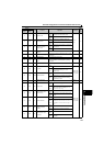
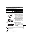
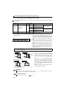
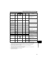
<Remote output data>
Pr.496
The output terminal can be turned ON/OFF depending on the
Pr.496 setting. The remote output selection can be controlled
ON/OFF by computer link communication from the PU
connector or by communication from the communication
option.
Set "96 (positive logic) or 196 (negative logic)" to any of Pr.190
to Pr.192 (output terminal function selection), and assign the
remote output (REM) signal to the terminal used for remote
output,
When you refer to the diagram on the left and set 1 to the
terminal bit (terminal where the REM signal has been
assigned) of Pr.496, the output terminal turns ON (OFF for
negative logic). By setting 0, the output terminal turns OFF
(ON for negative logic).
b11 b0
ABC
FU
RUN
Any
Example: When "96 (positive logic)" is set in Pr.190 RUN terminal function selection and "1" (H01) is set in Pr.496, the
terminal RUN turns ON.
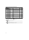
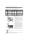
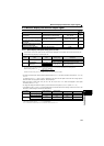
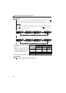
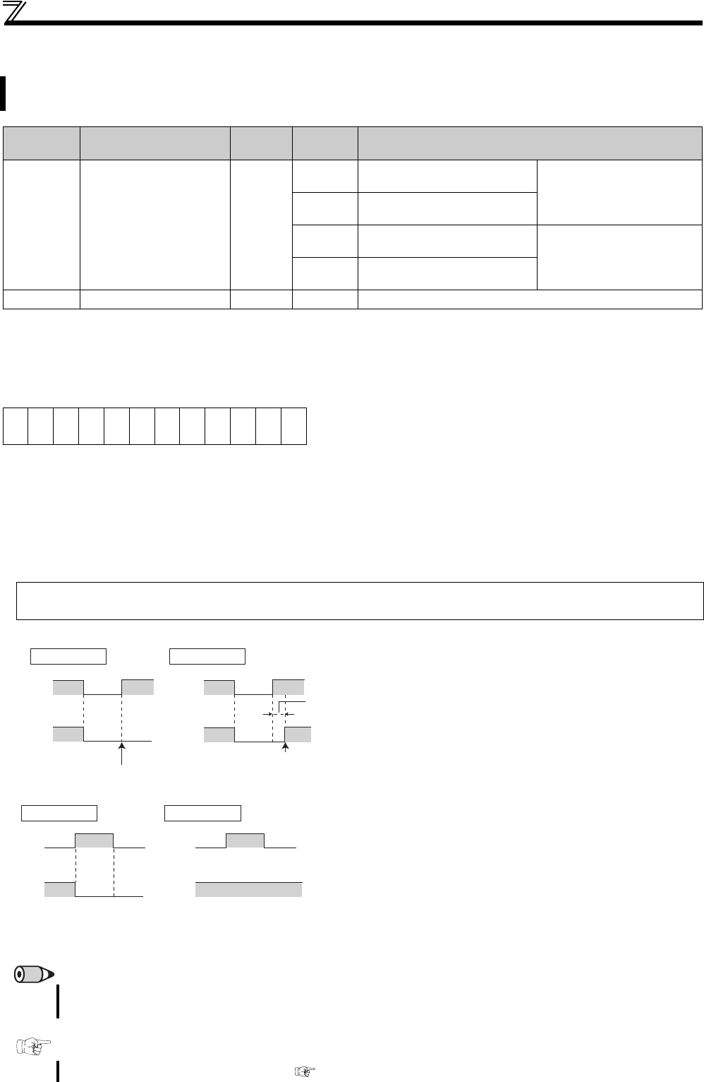
ON/OFF example for positive logic
Signal condition during a reset
When Pr.495 = "0 (initial value), 10", performing a power
ON reset (including a power failure) clears the REM
signal output. (The ON/OFF status of the terminals are
as set in Pr.190 to Pr.192. ) The Pr.496 settings are also
"0".
When Pr.495 = "1, 11", the remote output data before
power OFF is stored into the EEPROM, so the signal
output at power recovery is the same as before power
OFF. (See the chart on the left) However, it is not stored
when the drive unit is reset (terminal reset, reset request
through communication).
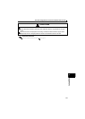
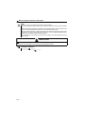
When Pr.495 = "10 or 11," the signal before the reset is
held even during a drive unit reset.
REMARKS
The output terminal where the REM signal is not assigned using any of Pr.190 to Pr.192 does not turn ON/OFF if 0/1 is set to the
terminal bit of Pr.496. (It turns ON/OFF with the assigned function.)
Parameter referred to
Pr.190 to Pr.192 (output terminal function selection) Refer to page 144
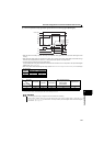
Power
supply
OFF OFF
ONOFF
REMREM
REM signal clear
REM signal held
Drive unit
reset time
(about 1s)
Power
supply
Pr.495 = 0, 10
Pr.495 = 1, 11
∗ When Pr.495 = "1," the signal condition saved in EEPROM (condition of
the last power OFF) is applied.
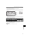
Reset
ON
ON OFF ONREMREM
Pr.495 = 0, 1 Pr.495 = 10, 11
Reset
ON
∗