77
4
PARAMETERS
PM sensorless vector control
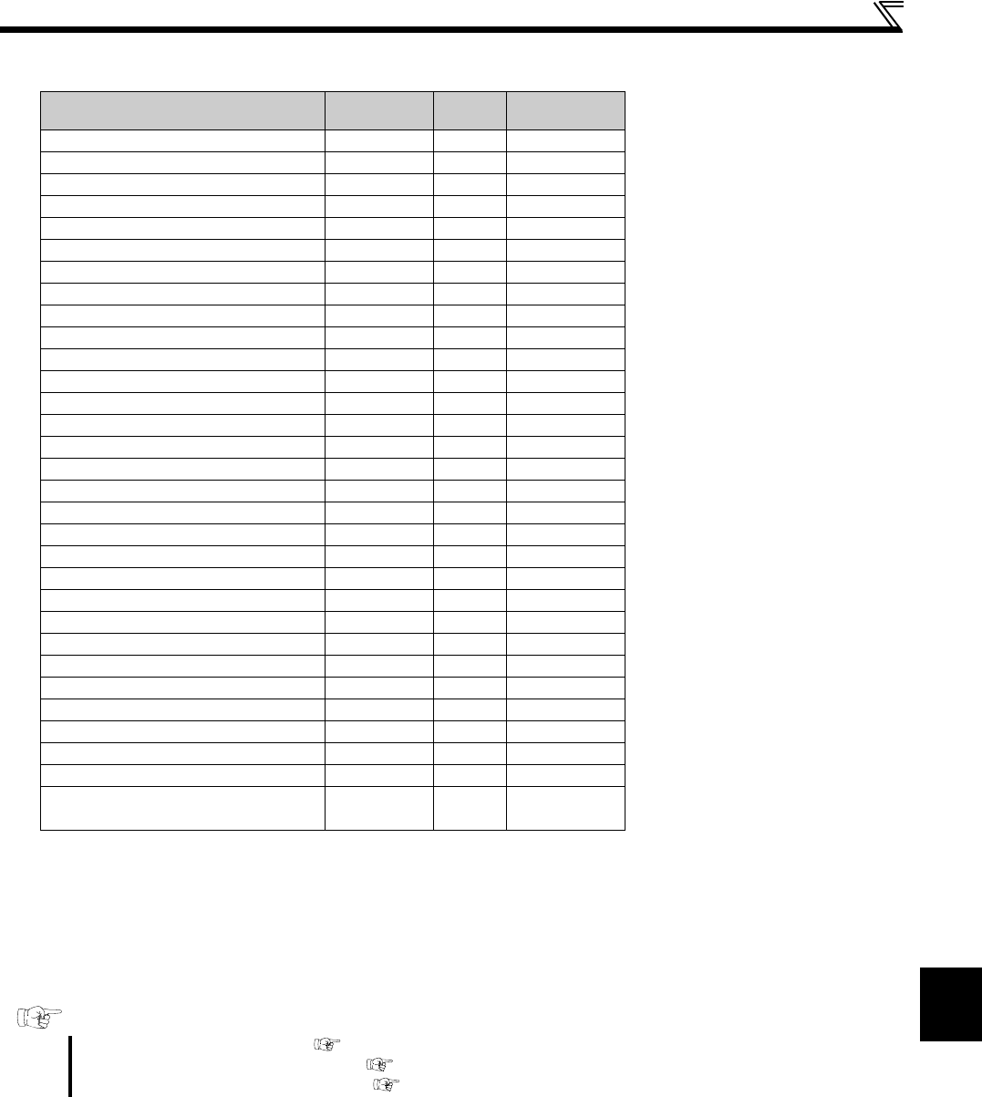
(3) Valid/invalid statuses of monitor outputs during the test operation
: Valid
: Invalid (always displays 0)
: Displays accumulated value before the test
— : Not monitored
Monitor output is valid or invalid depending on the monitor type (operation panel display, parameter unit display, or terminal FM/ AM). For details,
refer to page 155.
When the operation is switched to the test operation, "0" is displayed. When PM sensorless vector control is selected again after a test operation, the
output current peak value and the electronic thermal relay load factor from the last operation are displayed.
Monitoring items
DU/PU monitor
display
FM
output
Communication
Rotation speed
Output current
Output voltage
Fault display —
Speed setting value
Converter output voltage
Regenerative brake duty
Electronic thermal relay load factor
Output current peak value
Converter output voltage peak value
Output power
Position pulse
Cumulative energization time —
Reference voltage output — —
Actual operation time —
Motor load factor
Cumulative power —
Position command (upper/lower)
Current position (upper/lower)
Droop pulse (upper/lower)
Ideal speed command
Speed command
PID set point
PID measured value
PID deviation —
Input terminal status —/ —
Output terminal status —/ —
Drive unit I/O terminal status /— — —
Motor thermal relay load factor
Drive unit thermal relay load factor
Cumulative power
(for communication, in units of 0.01 kWh)
——
Parameters referred to
Pr.52 DU/PU main display data selection Refer to page 155
Pr.178 to Pr.184 (input terminal function selection) Refer to page 138
Pr.190 to Pr.192 (output terminal function selection) Refer to page 144


