


A-2
4. Additional Instructions
Also the following points must be noted to prevent an
accidental failure, injury, electric shock, etc.
(1) Transportation and Mounting
(2) Wiring
(3) Trial run
(4) Usage
The product must be transported in correct method that
corresponds to the weight. Failure to do so may lead to injuries.
Do not stack the boxes containing drive units higher than
the number recommended.
The product must be installed to the position where
withstands the weight of the product according to the
information in the Instruction Manual.
Do not install or operate the drive unit if it is damaged or has
parts missing.
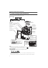
When carrying the drive unit, do not hold it by the front
cover or setting dial; it may fall off or fail.
Do not stand or rest heavy objects on the product.
The drive unit mounting orientation must be correct.
Foreign conductive objects must be prevented from
entering the drive unit. That includes screws and metal
fragments or other flammable substance such as oil.
As the drive unit is a precision instrument, do not drop or
subject it to impact.
The drive unit must be used under the following
environment. Otherwise the drive unit may be damaged.
Temperature applicable for a short time, e.g. in transit.
If halogen-based materials (fluorine, chlorine, bromine,
iodine, etc.) infiltrate into a Mitsubishi product, the product
will be damaged. Halogen-based materials are often
included in fumigant, which is used to sterilize or disinfest
wooden packages. When packaging, prevent residual
fumigant components from being infiltrated into Mitsubishi
products, or use an alternative sterilization or disinfection
method (heat disinfection, etc.) for packaging. Sterilization
of disinfection of wooden package should also be
performed before packaging the product.
Do not install a power factor correction capacitor or surge
suppressor/capacitor type filter on the drive unit output
side. These devices on the drive unit output side may be
overheated or burn out.
Correctly connect the output side terminals (terminals U, V,
and W).
PM motor terminals (U, V, W) hold high-voltage while the PM
motor is running even after the power is turned OFF. Before
wiring, the PM motor must be confirmed to be stopped.
Otherwise you may get an electric shock.
Never connect a PM motor to the commercial power supply.
Applying the commercial power supply to input terminals
(U, V, W) of a PM motor will burn the PM motor. The PM
motor must be connected with the output terminals (U, V, W)
of the drive unit.
CAUTION
Environment
Surrounding
air temperature
-10°C to +50°C (non-freezing)
Ambient
humidity
90%RH or less (non-condensing)
Storage
temperature
-20°C to +65°C
Atmosphere
Indoors (free from corrosive gas,
flammable gas, oil mist, dust and dirt)
Altitude/
vibration
Maximum 1,000m above sea level.
5.9m/s
2
or less at 10 to 55Hz (directions
of X, Y, Z axes
CAUTION
Before starting operation, each parameter must be
confirmed and adjusted. A failure to do so may cause some
machines to make unexpected motions.
A PM motor and the drive unit must be used in the specified
capacity combination.
Only one PM motor can be connected to a drive unit.
Any person must stay away from the equipment when the
retry function is set as it will restart suddenly after trip.
Since pressing key may not stop output depending on
the function setting status, separate circuit and switch that
make an emergency stop (power OFF, mechanical brake
operation for emergency stop, etc.) must be provided.
OFF status of the start signal must be confirmed before
resetting the drive unit fault. Resetting drive unit alarm with
the start signal ON restarts the motor suddenly.
Do not modify the equipment.
Do not perform parts removal which is not instructed in this
manual. Doing so may lead to fault or damage of the product.
The electronic thermal relay function does not guarantee
protection of the motor from overheating. It is
recommended to install both an external thermal and PTC
thermistor for overheat protection.
Do not use a magnetic contactor on the drive unit input for
frequent starting/stopping of the drive unit. Otherwise the
life of the drive unit decreases.
The effect of electromagnetic interference must be reduced
by using a noise filter or by other means. Otherwise nearby
electronic equipment may be affected.
Appropriate measures must be taken to suppress
harmonics. Otherwise power supply harmonics from the
drive unit may heat/damage the power factor correction
capacitor and generator.
When parameter clear or all parameter clear is performed, the
required parameters must be set again before starting
operations because all parameters return to the initial value.
The drive unit can be easily set for high-speed operation.
Before changing its setting, the performances of the motor
and machine must be fully examined.
Stop status cannot be hold by the drive unit's brake
function. In addition to the drive unit’s brake function, a
holding device must be installed to ensure safety.
Before running a drive unit which had been stored for a long
period, inspection and test operation must be performed.
Static electricity in your body must be discharged before you
touch the product. Otherwise the product may be damaged.
Do not use a PM motor in an application where a motor is
driven by its load and runs at a speed higher than the
maximum motor speed.
According to the motor to be connected, perform PM
parameter initialization. Incorrect initial setting of
parameters may damage the motor.
In the initial setting, FR-E720EX-0.1K to 0.75K is set for an
MM-GKR motor, and FR-E720EX-1.5K to 3.7K is set for an S-
PM geared motor.
Only use a motor that is a dedicated PM motor (MM-GKR
motor or S-PM geared motor).
In the system with a PM motor, the drive unit power must be
turned ON before closing the contacts of the contactor at
the output side.
CAUTION
WARNING
CAUTION