


2
Product checking and parts identification
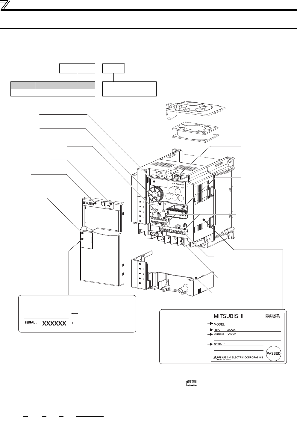
1.1 Product checking and parts identification
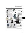
Unpack the drive unit and check the capacity plate on the front cover and the rating plate on the drive unit side face to ensure
that the product agrees with your order and the drive unit is intact.
Drive unit model
Accessory
Fan cover fixing screws (FR-E720EX-1.5K to 3.7K)(M335mm)...1
These screws are necessary for compliance with the EU Directive. (Refer to Instruction Manual (Basic))
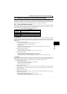
How to read SERIAL
Check the SERIAL number indicated on the drive unit rating plate or package.
FR - E720EX - 1.5 K
Symbol Voltage class
Represents the
drive unit capacity [kW]
E720EX Three-phase 200V class
Rating plate example
Symbol Year Month Control number
SERIAL (Serial No.)
The SERIAL consists of 1 version symbol, 2 numeric characters or 1 numeric character and 1 alphabet letter indicating year and month, and
6 numeric characters indicating control number.
Last digit of the production year is indicated as the Year, and the Month is indicated by 1 to 9, X (October), Y (November), and Z (December).
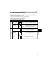
Drive unit model
Serial number
Capacity plate
Input rating
Output rating
Serial number
Rating plate
Drive unit model
Production year and month
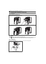
FR-E720EX-1.5K
FR-E720EX-1.5K
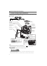
Connector for plug-in
option connection
(Refer to the instruction
manual of options.)
USB connector
(mini-B connector)
(Refer to page 234)
Control circuit
terminal block
(Refer to page 18)
Changing the control logic
jumper connector
(Refer to page 21)
Combed shaped wiring cover
(Refer to page 6)
Main circuit terminal block
(Refer to page 15)
PU connector cover
(Refer to page 25)
Front cover
(Refer to page 6)
USB connector cover
Voltage/current input switch
(Refer to page 18)
Operation panel
(Refer to page 48)
PU connector
(Refer to page 20)
For the location of the capacity plate and rating plate, refer
to the outline dimension. (Refer to page 305)
Example of FR-E720EX-1.5K
Cooling fan
(Refer to page 292)