


31
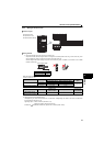
Connection of stand-alone option unit
2
WIRING
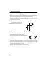
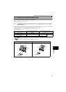
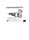
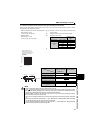
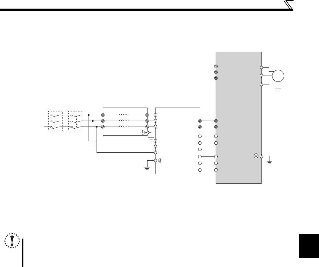
2.4.4 Connection of the power regeneration common converter (FR-CV)
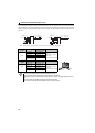
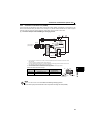
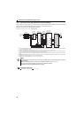
When connecting the power regeneration common converter (FR-CV), connect the drive unit terminals (P/+, N/-) and power
regeneration common converter (FR-CV) terminals as shown below so that their symbols match with each other.
Keep input terminals (R/L1, S/L2, T/L3) open. Incorrect connection will damage the drive unit.
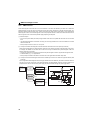
Do not insert an MCCB between the terminals P/+ and N/- (between P/L+ and P/+, between N/L- and N/-). Opposite polarity of terminals
N/- and P/+ will damage the drive unit.
Use Pr.178 to Pr.184 (input terminal function selection) to assign the terminals used for the X10, RES signal. (Refer to page 138)
Always connect the power supply and terminals R/L11, S/L21, T/MC1.
Operating the drive unit without connecting them will damage the power regeneration common converter.
Be sure to connect terminal RDYB of the FR-CV to the X10 signal or MRS signal assigned terminal of the drive unit, and connect terminal
SE of the FR-CV to terminal SD of the drive unit. Without proper connecting, FR-CV will be damaged.
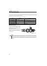
NOTE
The voltage phases of terminals R/L11, S/L21, T/MC1 and terminals R2/L1, S2/L2, T2/L3 must be matched.
Use sink logic (factory setting) when the FR-CV is connected. The FR-CV cannot be connected when source logic is
selected.
Do not connect a DC reactor (FR-HEL) to the drive unit when FR-CV is connected.
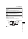
R/L11
Dedicated stand-alone
reactor (FR-CVL)
S/L
21
T/L31
R2/L12
S2/L22
T2/L32
R2/L1
S2/L2
T2/L3
R/L11
S/L21
T/MC1
P/L+
U
V
W
M
FR-CV type power
regeneration
common converter
Drive unit
PC
SD
X10
RES
SD
P24
SD
RDYB
RSO
SE
RDYA
N/L-
R/L1
S/L2
T/L3
P/+
N/-
Three-phase
A
C power supply
MCCB
MC
1