


240
Special operation and speed control
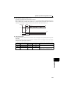
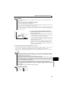
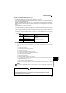
(7) Adjustment procedure
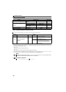
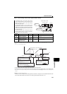
(8) Calibration example
(A detector of 4mA at 0°C and 20mA at 50°C is used to adjust the room temperature to 25°C under PID control.
The set point is given to across drive unit terminals 2-5 (0 to 5V).)
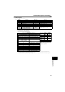
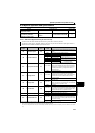
Parameter setting Adjust the PID control parameters, Pr.127 to Pr.134.
Terminal setting
Set the I/O terminals for PID control (Pr.178 to Pr.184 (input terminal
function selection), Pr.190 to Pr.192 (output terminal function selection))
Turn ON the X14 signal.
When X14 signal is not assigned, setting a value other than "0" in
Pr.128 activates PID operation.
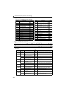
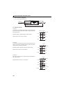
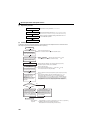
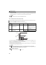
Operation
Start
Determination of set point
Determine the set point of
what is desired to be adjusted.
Conversion of set point into %
Calculate the ratio of the set
point to the detector output.
Make calibration.
Setting of set point
Operation
Is the set point stable?
Parameter adjustment Parameter optimization
Adjustment end
Yes
No
∗When calibration
is required
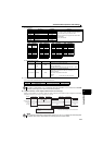
Set the proportional band (Pr.129 )
to a slightly larger value, the
integral time (Pr.130 ) to a
slightly longer time, and the
differential time (Pr.134 ) to "9999"
(no function), and turn ON the
start signal.
To stabilize the measured value,
change the proportional band
(Pr.129 ) to a larger value, the
integral time (Pr. 130 ) to a slightly
longer time, and the differential
time (Pr.134 ) to a slightly shorter
time.
While the measured value is stable
throughout the operation status, the
proportional band (Pr.129 ) may be
decreased, the integral time (Pr.130 )
decreased, and the differential time
(Pr.134 ) increased.
When the parameter unit is used for operation, input the set point (0 to 100%)
in Pr.133.
When performing operation, first set the proportional band (Pr.129 ) to a
slightly larger value, the integral time (Pr.130 ) to a slightly longer time,
and the differential time (Pr.134 ) to "9999" (no function), and while looking at
the system operation, decrease the proportional band (Pr.129 ) and increase
the integral time (Pr.130 ). For slow response system where a deadband
exists, differential control (Pr.134 ) should be turned ON and increased slowly.
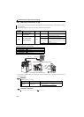
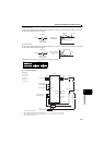
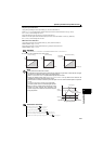
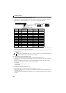
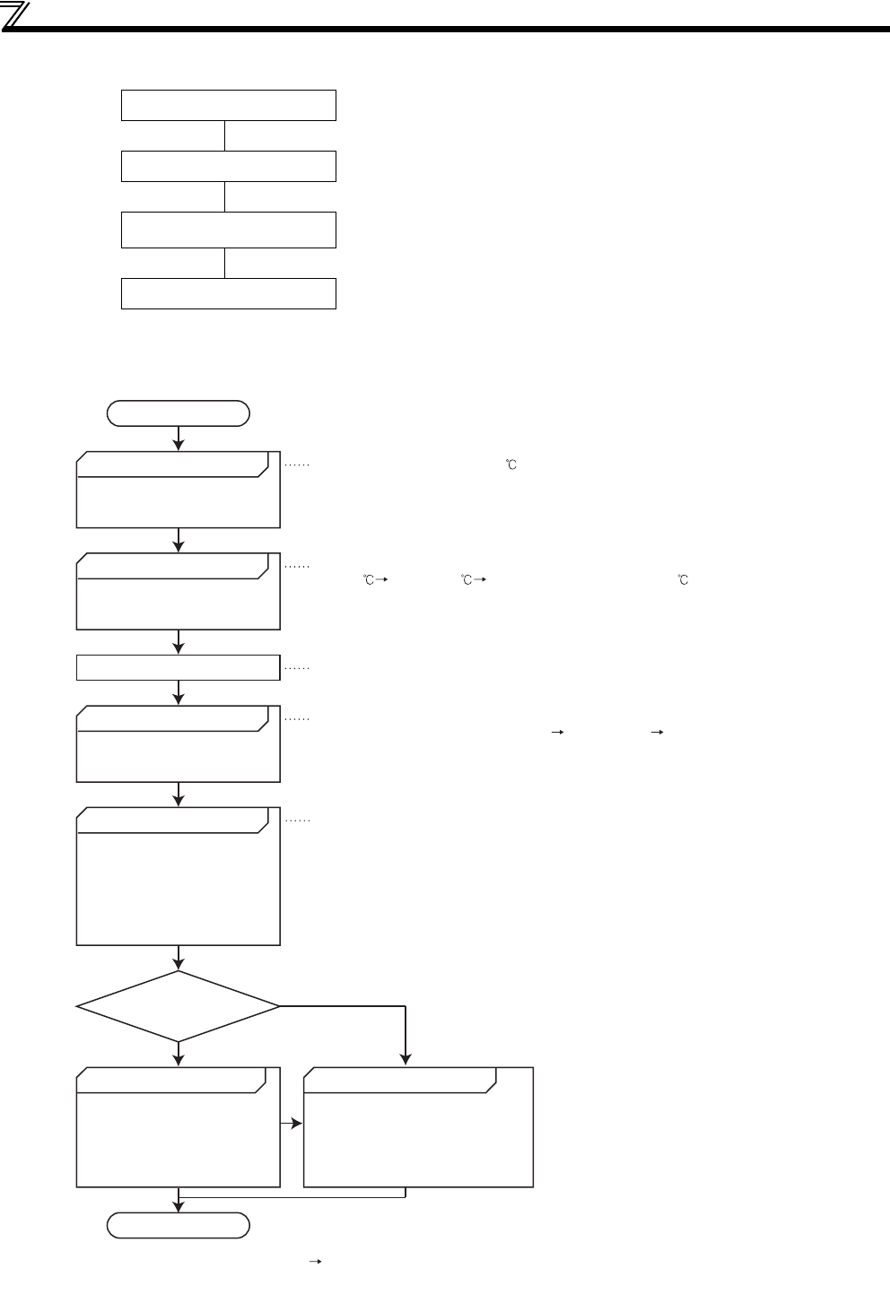
Make the following calibration∗ when the target setting input (0 to 5V)
and etector output (4 to 20mA) must be calibrated.
Input a voltage across terminals
2-5 according to the set value %.
Using calibration Pr.902 and Pr.903 (terminal 2) or Pr.904 and Pr.905 (terminal 4),
calibrate the detector output and target setting input.
Make calibration in the PU mode during an drive unit stop.
Set the room temperature to 25 .
Set Pr.128 and turn ON the X14 signal to enable PID control.
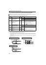
Detector specifications
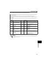
When 0 4mA and 50 20mA are used, the set point 25 is 50%
on the assumption that 4mA is 0% and 20mA is 100%.
When the set point is 50%
As the terminal 2 specifications are 0% 0V and 100% 5V, input
2.5V to the terminal 2 for the set point of 50%.