


18
Control circuit specifications
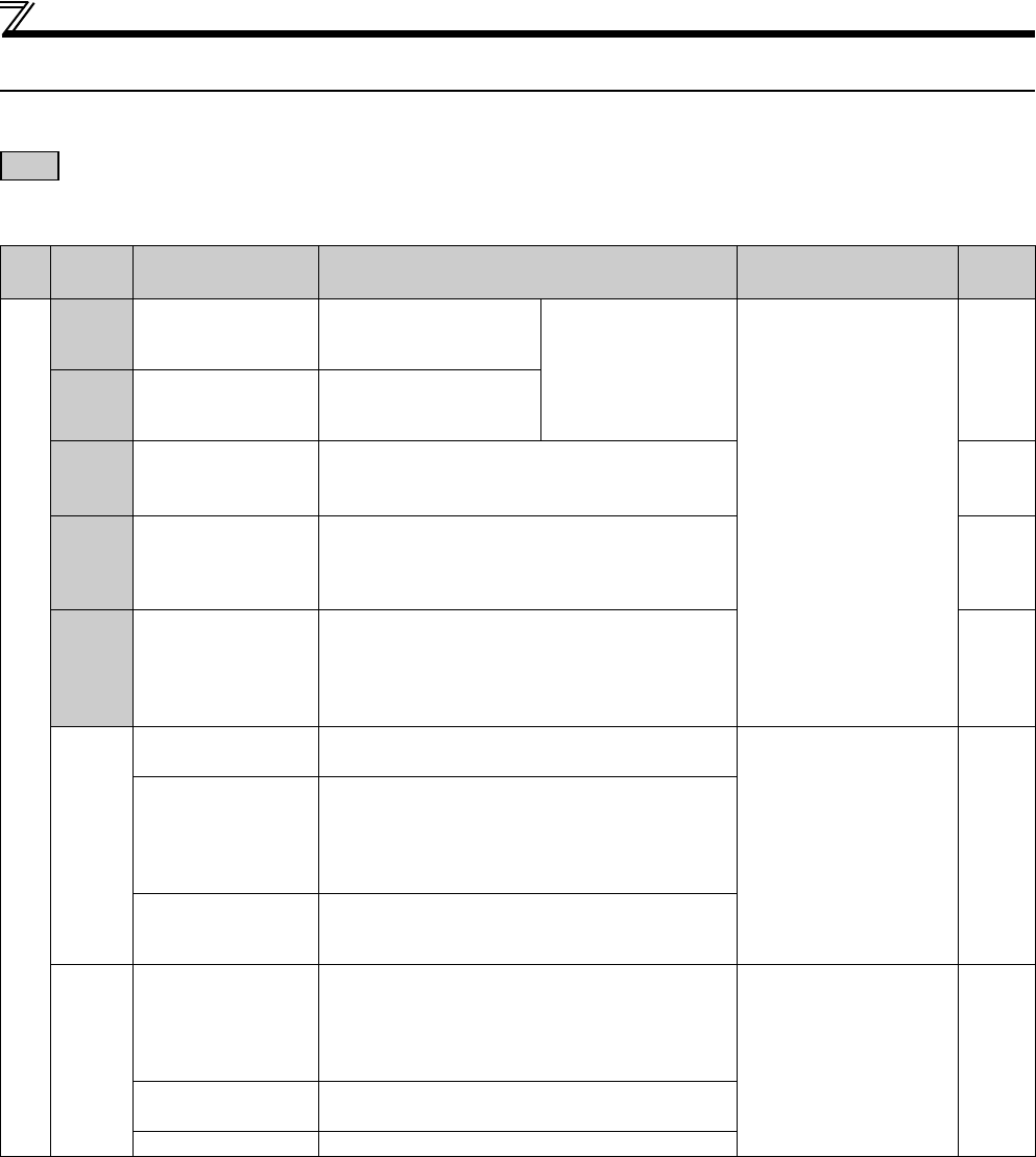
2.3 Control circuit specifications
2.3.1 Control circuit terminal
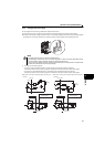
indicates that terminal functions can be selected using Pr.178 to Pr.184, Pr.190 to Pr.192 (I/O terminal function selection).
(Refer to page 138)
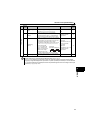
(1) Input signal (Speed control)
Type
Terminal
Symbol
Terminal Name Description Rated Specifications
Refer to
Page
Contact input
STF Forward rotation start
Turn ON the STF signal to
start forward rotation and
turn it OFF to stop.
When the STF and STR
signals are turned ON
simultaneously, the stop
command is given.
Input resistance 4.7k
Voltage at opening
21 to 26VDC
Current at short-circuited
4 to 6mADC
142
STR Reverse rotation start
Turn ON the STR signal to
start reverse rotation and
turn it OFF to stop.
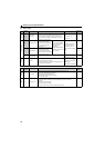
RH,
RM,
RL
Multi-speed selection
Multi-speed can be selected according to the
combination of RH, RM and RL signals.
117
MRS Output stop
Turn ON the MRS signal (20ms or more) to stop the
drive unit output.
Use to shut off the drive unit output when stopping the
motor by electromagnetic brake.
140
RES Reset
Use to reset fault output provided when fault occurs. Turn
ON the RES signal for more than 0.1s, then turn it OFF.
In the initial status, reset is set always-enabled. By setting
Pr.75, reset can be set enabled only at fault occurrence.
Recover about 1s after reset is cancelled.
178
SD
Contact input common
(sink) (initial setting)
Common terminal for contact input terminal (sink logic)
and terminal FM.
——
External transistor
common (source)
When connecting the transistor output (open collector
output), such as a programmable controller, when
source logic is selected, connect the external power
supply common for transistor output to this terminal to
prevent a malfunction caused by undesirable currents.
24VDC power supply
common
Common output terminal for 24VDC 0.1A power supply
(PC terminal).
Isolated from terminals 5 and SE.
PC
External transistor
common (sink)
(initial setting)
When connecting the transistor output (open collector
output), such as a programmable controller, when sink
logic is selected, connect the external power supply
common for transistor output to this terminal to prevent
a malfunction caused by undesirable currents.
Power supply voltage range
22 to 26.5VDC
permissible load current
100mA
21
Contact input common
(source)
Common terminal for contact input terminal (source
logic).
24VDC power supply Can be used as 24VDC 0.1A power supply.