


277
5
TROUBLESHOOTING
Causes and corrective actions
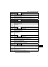
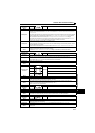
Operation panel
indication
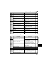
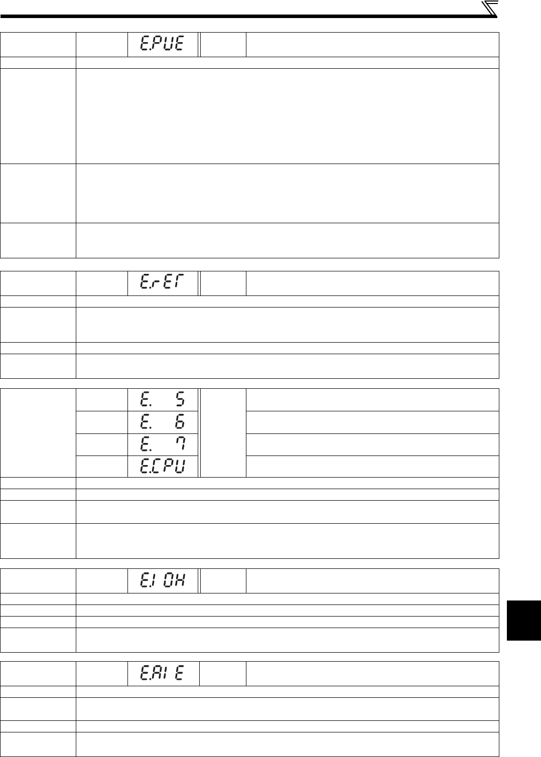
E.PUE
FR-PU07 PU Leave Out
Name
PU disconnection
Description
This function stops the drive unit output if communication between the drive unit and PU is suspended, e.g. the
parameter unit is disconnected, when "2", "3", "16" or "17" was set in Pr.75 Reset selection/disconnected PU detection/
PU stop selection.
This function stops the drive unit output when communication errors occurred consecutively for more than permissible
number of retries when a value other than "9999" is set in
Pr.121 Number of PU communication retries
during the RS-
485 communication with the PU connector (use
Pr.502 Stop mode selection at communication error
to change).
This function also stops the drive unit output if communication is broken within the period of time set in Pr.122 PU
communication check time interval during the RS-485 communication with the PU connector.
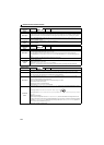
Check point
Check that the parameter unit (FR-PU07) is connected properly.
Check the Pr.75 setting.
Check that RS-485 communication data is correct. And check that the settings of communication parameter at drive
unit match settings of the computer.
Check that data is transmitted from the computer within a time set in Pr.122 PU communication check time interval.
Corrective
action
Connect the parameter unit (FR-PU07) securely.
Check the communication data and communication settings.
Increase the Pr.122 PU communication check time interval setting. Or set "9999" (no communication check).
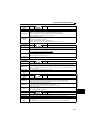
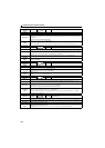
Operation panel
indication
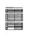
E.RET
FR-PU07 Retry No Over
Name
Retry count excess
Description
If operation cannot be resumed properly within the number of retries set, this function trips the drive unit.
This function is available only when Pr.67 Number of retries at fault occurrence is set.
When the initial value (Pr.67 = "0") is set, this protective function is not available.
Check point
Find the cause of fault occurrence.
Corrective
action
Eliminate the cause of the error preceding this error indication.
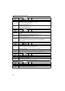
Operation panel
indication
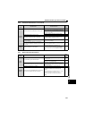
E. 5
FR-PU07
Fault 5
E. 6
Fault 6
E. 7 Fault 7
E.CPU CPU Fault
Name
CPU fault
Description
Stops the drive unit output if the communication fault of the built-in CPU occurs.
Check point
Check for devices producing excess electrical noises around the drive unit.
Check if the terminal PC is shorted with the terminal SD. (E. 6/E. 7)
Corrective
action
Take measures against noises if there are devices producing excess electrical noises around the drive unit.
Check the connection between the terminals PC and SD. (E. 6/E. 7)
Please contact your sales representative.
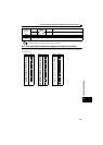
Operation panel
indication
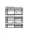
E.IOH
FR-PU07 Inrush overheat
Name
Inrush current limit circuit fault
Description
Stops the drive unit output when the resistor of inrush current limit circuit overheated. The inrush current limit circuit fault
Check point
Check that frequent power ON/OFF is not repeated.
Corrective
action
Configure a circuit where frequent power ON/OFF is not repeated.
If the problem still persists after taking the above measure, please contact your sales representative.
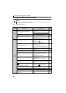
Operation panel
indication
E.AIE
FR-PU07 Analog in error
Name
Analog input fault
Description
Appears if voltage(current) is input to terminal 4 when the setting in Pr.267 Terminal 4 input selection and the setting of
voltage/current input switch are different.
Check point
Check the setting of Pr.267 Terminal 4 input selection and voltage/current input switch. (Refer to page 168)
Corrective
action
Either give a speed command by current input or set Pr.267 Terminal 4 input selection, and voltage/current input switch
to voltage input.