


23
2
WIRING
Control circuit specifications
2.3.3 Wiring of control circuit
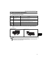
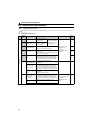
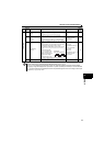
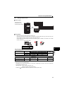
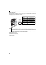
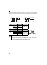
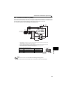
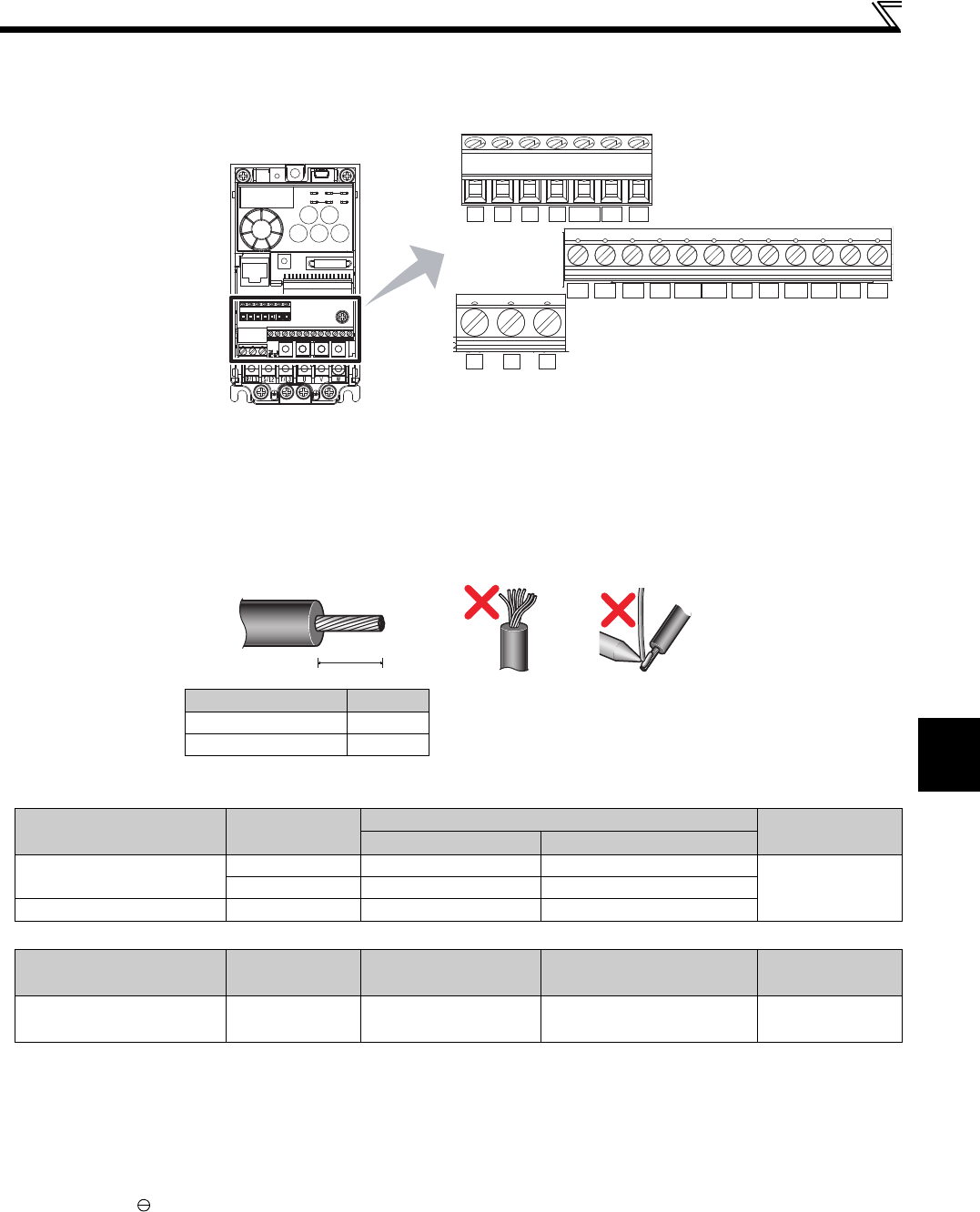
Terminal layout
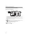
Wiring method
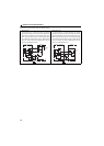
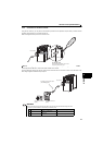
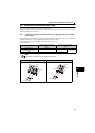
1) Strip off the sheath of the wire of the control circuit to wire.
Strip off the sheath about the length below. If the length of the sheath peeled is too long, a short circuit may occur
among neighboring wires. If the length is too short, wires might come off.
Wire the stripped wire after twisting it to prevent it from becoming loose. In addition, do not solder it. Use a blade
terminal as necessary.
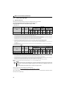
Blade terminals available on the market: (as of Feb. 2012)
Phoenix Contact Co.,Ltd.
NICHIFU Co.,Ltd.
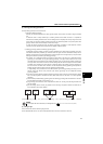
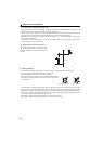
2) Loosen the terminal screw and insert the wire into the terminal.
3) Tighten the screw to the specified torque.
Undertightening can cause wire disconnection or malfunction. Overtightening can cause a short circuit or malfunction
due to damage to the screw or unit.
Tightening torque: 0.5N·m to 0.6N·m (terminal A, B, C)
0.22N·m to 0.25N·m (other than the above)
Screwdriver: Small flathead screwdriver (Tip thickness: 0.4mm/tip width: 2.5mm)
Terminal screw size
M3: (Terminal A, B, C)
M2: (Other than the above)
Wire stripping length
L(mm)
Terminal A, B, C 6
Other than the above 5
Terminal Screw Size
Wire Size (mm
2
)
Blade Terminal Model Crimping Tool
Name
With Insulation Sleeve Without Insulation Sleeve
M3 (terminal A, B, C)
0.3, 0.5 AI 0,5-6WH A 0,5-6
CRIMPFOX 6
0.75 AI 0,75-6GY A 0,75-6
M2 (other than the above)
0.3, 0.5 AI 0,5-6WH A 0,5-6
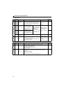
Terminal Screw Size
Wire Size (mm
2
)
Blade terminal
product number
Insulation product number
Crimping Tool
Product Number
M3 (terminal A, B, C)
M2 (other than the above)
0.3 to 0.75 BT 0.75-7 VC 0.75 NH 69
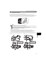
SDSD
STF STR
PCSD
RESMRS
RHRMRL
FM
CBA
10 2 5 4 RUN FU SE
L