


281
Check first when you have a trouble
5
TROUBLESHOOTING
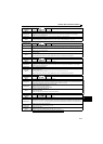
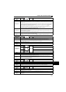
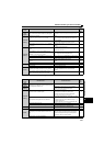
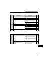
5.5.2 Motor or machine is making abnormal acoustic noise
Input
Signal
Under position control, the forward rotation stroke end
(LSP) or the reverse rotation stroke end (LSN) signal is
assigned, but is not input.
Turn ON the LSP or LSN signal.
Check the Pr.535 Position control terminal input selection
setting.
100
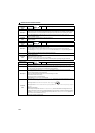
Parameter
Setting
Pr.78 Reverse rotation prevention selection is set.
Check the Pr.78 setting.
Set Pr.78 when you want to limit the motor rotation to
only one direction.
182
Pr.79 Operation mode selection setting is wrong.
Select the operation mode which corresponds with input
methods of start command and speed command.
188
Bias and gain (calibration parameter C2 to C7) settings
are improper.
Check the bias and gain (calibration parameter C2 to C7)
settings.
173
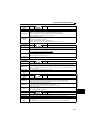
Parameter
Setting
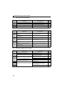
Pr.13 Starting speed setting is greater than the running
speed.
Set running speed higher than Pr.13.
The drive unit does not start if the speed setting signal is
less than the value set in Pr.13.
128
Speed settings of various running speed (such as
multispeed operation) are zero.
Especially, Pr.1 Maximum setting is zero.
Set the speed command according to the application.
Set Pr.1 higher than the actual speed used.
115
Pr.15 Jog speed setting is lower than Pr.13 Starting speed. Set Pr.15 Jog speed setting higher than Pr.13 Starting speed. 119
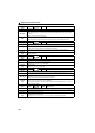
Operation mode and a writing device do not match.
Check Pr.79, Pr.338, Pr.339, Pr.551, and select an
operation mode suitable for the purpose.
186,
195
Start signal operation selection is set by the Pr.250 Stop
selection.
Check Pr.250 setting and connection of STF and STR
signals.
142
PM motor test operation is selected. Set "10" in Pr.800 Control method selection. 75
Load
Load is too heavy. Reduce the load.
Shaft is locked. Inspect the machine (motor).
Others
Operation panel display shows an error (e.g. E.OC1).
When any fault occurs, take an appropriate corrective
action, then reset the drive unit, and resume the
operation.
267
Under position control, point table position control
based on the absolute position does not operate.
Perform home position return. 95, 104
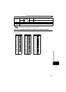
Check
Points
Possible Cause Countermeasures
Refer
to
page
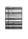
Input
Signal
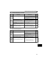
Disturbance due to EMI when speed command is given
from analog input (terminal 2, 4).
Take countermeasures against EMI. 36
Parameter
Setting
Increase the Pr.74 Input filter time constant if steady
operation cannot be performed due to EMI.
172
Parameter
Setting
Resonance occurs. (rotation speed)
Set Pr.31 to Pr.36 (speed jump).
When it is desired to avoid resonance attributable to the
natural speed of a mechanical system, these
parameters allow resonant speeds to be jumped.
Set Pr.862, Pr.863, and Pr.871 (notch filter).
85, 116
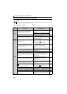
Gain adjustment during PID control is insufficient.
To stabilize the measured value, change the proportional
band (Pr.129 ) to a larger value, the integral time (Pr.130 )
to a slightly longer time, and the differential time (Pr.134 )
to a slightly shorter time.
Check the calibration of set point and measured value.
235
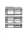
Speed control gain is too high. Check Pr.820 Speed control P gain setting. 80
Under position control, position control gain is too high. Check the Pr.422 Position control gain setting. 92
Others
Mechanical looseness
Adjust machine/equipment so that there is no
mechanical looseness.
Motor
Operating with output phase loss Check the motor wiring.
High-frequency tone is heard while the motor is at a
stop.
High-frequency tone may be generated during the MM-
GKR motor driving operation because high frequency
currents are superposed during low-speed operation
and stopping. This is a normal operation.
Please contact your sales representative.
Check
Points
Possible Cause Countermeasures
Refer
to
page