


238
Special operation and speed control
(4) I/O signals and parameter setting
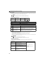
Set "20, 21, 50, 51, 60 or 61" in Pr.128 to perform PID operation.
Set "14" in any of Pr.178 to Pr.184 (input terminal function selection) to assign PID control selection signal (X14) to turn the
X14 signal ON.
When the X14 signal is not assigned, only the Pr.128 setting makes PID control valid.
Enter the set point using the drive unit terminal 2 or Pr.133 and enter the measured value to terminal 4.
REMARKS
When Pr.128 = "0" or X14 signal is OFF, normal drive unit operation is performed without PID action.
Turning ON/OFF of bit of the terminal, to which X14 signal is assigned through network as RS-485 communication, enables
PID control.
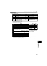
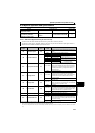
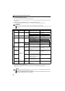
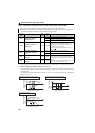
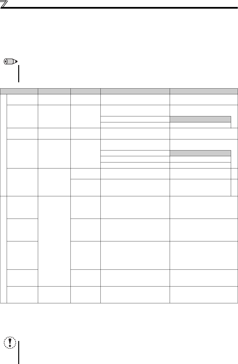
Signal Terminal Used Function Description Parameter Setting
Input
X14
Depending on
Pr.178 to Pr.184
PID control
selection
Turn ON X14 signal to perform PID
control.
Set 14 in any of Pr.178 to Pr.184.
2 2 Set point input
You can input the set point for PID
control.
Pr.128 = 20, 21,
Pr.133 = 9999
0 to 5V.............0 to 100%
Pr.73 = 1, 11
0 to 10V...........0 to 100%
Pr.73 = 0, 10
PU Set point input
Set the set point (Pr.133) from the
operation panel.
Pr.128 = 20, 21,
Pr.133 = 0 to 100%
44
Measured
value input
Input the signal from the detector
(measured value signal).
Pr.128 = 20, 21
4 to 20mA........0 to 100%
Pr.267 = 0
0 to 5V.............0 to 100%
Pr.267 = 1
0 to 10V...........0 to 100%
Pr.267 = 2
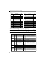
Communication
Deviation
value input
Inputs the deviation value from CC-
Link communication.
Pr.128 = 50, 51
Set point,
measured
value input
Inputs the set point and deviation
value from CC-Link communication.
Pr.128 = 60, 61
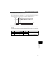
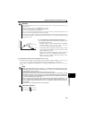
Output
FUP
Depending on
Pr.190 to Pr.192
Upper limit
output
Output to indicate that the measured
value signal exceeded the maximum
value (Pr.131).
Pr.128 = 20, 21, 60, 61
Pr.131 9999
Set 15 or 115 in any of Pr.190 to Pr.192
FDN
Lower limit
output
Output when the measured value
signal falls below the minimum value
(Pr.132).
Pr.128 = 20, 21, 60, 61
Pr.132 9999
Set 14 or 114 in any of Pr.190 to
Pr.192.
RL
Forward
(reverse)
rotation
direction
output
"Hi" is output to indicate that the output
indication of the parameter unit is
forward rotation (FWD) or "Low" to
indicate that it is reverse rotation
(REV) or stop (STOP).
Set 16 or 116 in any of Pr.190 to
Pr.192.
PID
During PID
control
activated
Turns ON during PID control.
Set 47 or 147 in any of Pr.190 to
Pr.192.
SE SE
Output
terminal
common
Common terminal for open collector
output terminal.
When the X14 signal is not assigned, only the Pr.128 setting makes PID control valid.
The shaded area indicates the parameter initial value.
Refer to the CC-Link communication option (FR-A7NC E kit) instruction manual for the setting method from CC-Link communication.
When 100 or larger value is set in any of Pr.190 to Pr.192 (output terminal function selection), the terminal output has negative logic. (For details refer to
page 144)
NOTE
Changing the terminal function using any of Pr.178 to Pr.184 and Pr.190 to Pr.192 may affect the other functions. Set
parameters after confirming the function of each terminal.
When the Pr.267 setting was changed, check the voltage/current input switch setting. Different setting may cause a
fault, failure or malfunction. (Refer to page 168 for setting)