


Parameter listParameter list
56
P
a
r
a
m
e
t
e
r
L
i
s
t
4
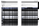
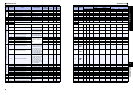
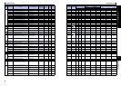
PARAMETERS
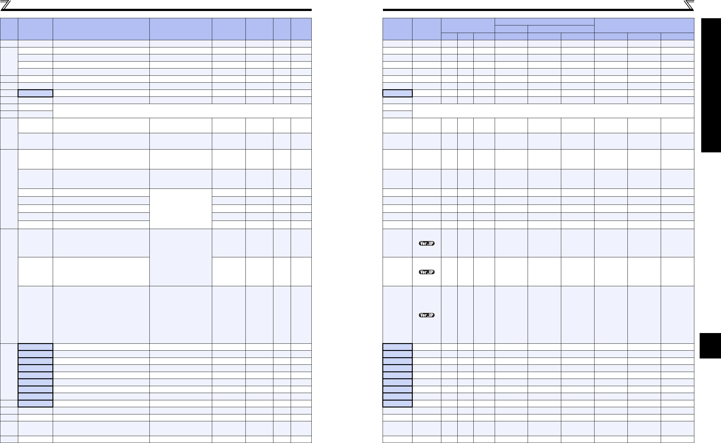
149 Torque limit level at 20mA input 0 to 200% 0.1% 200% 111 149 31 B1 1
Current
detection
150 Output current detection level 0 to 200% 0.1% 150% 150 150 32 B2 1
151 Output current detection signal delay time 0 to 10s 0.1s 0s 150 151 33 B3 1
152 Zero current detection level 0 to 200% 0.1% 5% 150 152 34 B4 1
153 Zero current detection time 0 to 1s 0.01s 0.5s 150 153 35 B5 1
156 Torque limit selection 0 to 31, 100, 101 1 0 111 156 38 B8 1
157 OL signal output timer 0 to 25s, 9999 0.1s 0s 111 157 39 B9 1
160 Extended function display selection 0, 9999 1 0 182 160 00 80 2
161 Speed setting/key lock operation selection 0, 1, 10, 11 1 0 256 161 01 81 2
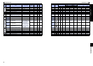
168
Parameter for manufacturer setting. Do not set.
168
Parameter for manufacturer setting. Do not set.
169 169
Cumulative
monitor clear
170 Watt-hour meter clear 0, 10, 9999 1 9999 155 170 0A 8A 2
171 Operation hour meter clear 0,9999 1 9999 155 171 0B 8B 2
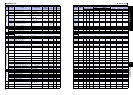
Input terminal function assignment
178 STF terminal function selection
0 to 5, 7, 8, 10, 12, 14, 16, 23
to 25, 29, 30, 44, 60, 62,
65 to 67, 76, 86 to 89, 9999
160138 178 12 92 2
179 STR terminal function selection
0 to 5, 7, 8, 10, 12, 14, 16, 23
to 25, 29, 30, 44, 61 62,
65 to 67, 76, 86 to 89, 9999
1 61 138 179 13 93 2
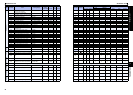
180 RL terminal function selection
0 to 5, 7, 8, 10, 12, 14,
16, 23 to 25, 29, 30, 44,
62, 65 to 67, 76, 86 to 89,
9999
10138 180 14 94 2
181 RM terminal function selection 1 1 138 181 15 95 2
182 RH terminal function selection 1 2 138 182 16 96 2
183 MRS terminal function selection 1 24 138 183 17 97 2
184 RES terminal function selection 1 62 138 184 18 98 2
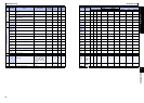
Output terminal function assignment
190 RUN terminal function selection
0, 1, 3, 4, 7, 8, 11 to 16, 21, 24
to 26, 33, 36, 38, 47, 55, 56,
60, 61, 63, 64, 68, 90, 91, 93,
95, 96, 98, 99, 100, 101, 103,
104, 107, 108, 111 to 116,
121, 124 to 126, 133, 136,
138, 147, 155, 156, 160, 161,
163, 164, 168, 190, 191, 193,
195, 196, 198, 199, 9999
1 0 144 190 1E 9E 2
191 FU terminal function selection 1 4 144 191 1F 9F 2
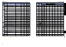
192 ABC terminal function selection
0, 1, 3, 4, 7, 8, 11 to 16, 21, 24
to 26, 33, 36, 38, 47, 55, 56,
60, 61, 63, 64, 68, 90, 91, 95,
96, 98, 99, 100, 101, 103,
104, 107, 108, 111 to 116,
121, 124 to 126, 133, 136,
138, 147, 155, 156, 160, 161,
163, 164, 168, 190, 191, 195,
196, 198, 199, 9999
1 99 144 192 20 A0 2
Multi-speed setting
232 Multi-speed setting (speed 8) 0 to 4800r/min , 9999 1r/min 9999 117 232 28 A8 2
233 Multi-speed setting (speed 9) 0 to 4800r/min , 9999 1r/min 9999 117 233 29 A9 2
234 Multi-speed setting (speed 10) 0 to 4800r/min , 9999 1r/min 9999 117 234 2A AA 2
235 Multi-speed setting (speed 11) 0 to 4800r/min , 9999 1r/min 9999 117 235 2B AB 2
236 Multi-speed setting (speed 12) 0 to 4800r/min , 9999 1r/min 9999 117 236 2C AC 2
237 Multi-speed setting (speed 13) 0 to 4800r/min , 9999 1r/min 9999 117 237 2D AD 2
238 Multi-speed setting (speed 14) 0 to 4800r/min , 9999 1r/min 9999 117 238 2E AE 2
239 Multi-speed setting (speed 15) 0 to 4800r/min , 9999 1r/min 9999 117 239 2F AF 2
241 Analog input display unit switchover 0, 1 1 0 173 241 31 B1 2
244 Cooling fan operation selection 0, 1 1 1 245 244 34 B4 2
249 Earth (ground) fault detection at start 0, 1 1 0 166 249 39 B9 2
250 Stop selection
0 to 100s, 1000 to 1100s,
8888, 9999
0.1s 9999
137,
142
250 3A BA 2
251 Output phase loss protection selection 0, 1 1 1 166 251 3B BB 2
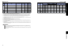
Function
Parameter Name Setting Range
Minimum
Setting
Increments
Initial
Value
Refer
to
Page
Customer
Setting
Parameter Remarks
Instruction Code
Motor/Control Mode Support Table
Parameter
S-PM MM-GKR
Read Write
Extended
Speed Speed position Copy Clear All clear