


89
4
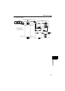
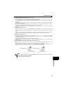
PARAMETERS
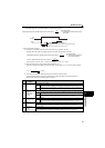
Position control
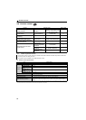
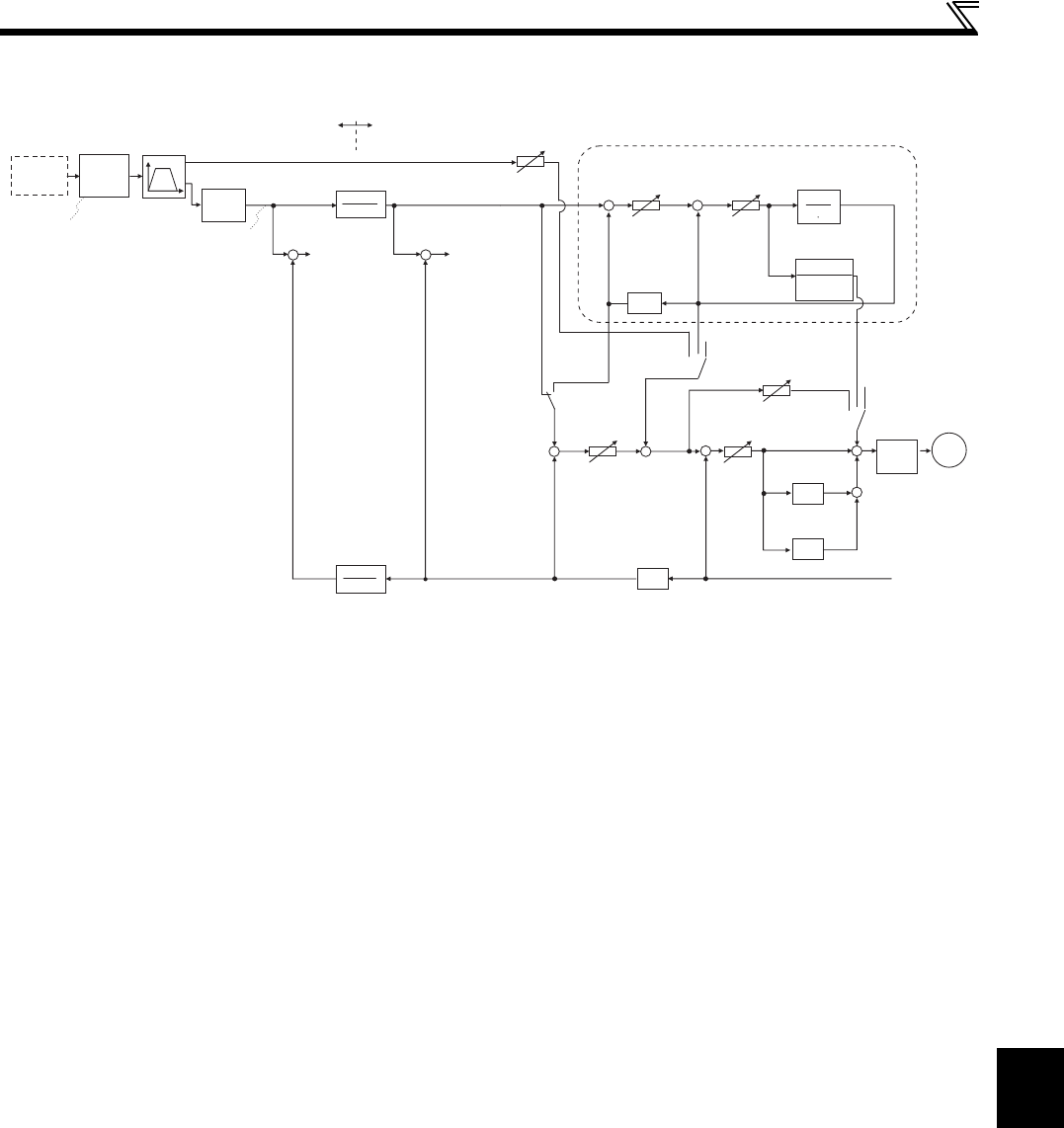
(2) Control block diagram
RH signal
Point
table
selection
RM signal
RL signal
Speed command
created
Target position
[Before electronic gear]
Travel
distance
created
Position command
[Before
electronic gear]
+
-
Indication category of position data
[Before electronic gear] [After electronic gear]
Electronic gear
Pr.420
Pr.421
+
-
Droop pulse
[After electronic
gear]
Droop pulse
[Before
electronic gear]
Current position
[After electronic gear]
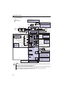
Ideal speed command
Position feed
forward gain
Pr.423
Model adaptive speed control (Pr.877 = 2)
Model position
control gain
Pr.446
Model speed
control gain
Pr.828
Model speed
calculation
+
-
+
-
Load inertia ratio
Pr.880
Model position
Model speed
1
J s
J
Torque
coefficient
02
0
Speed feed forward
gain Pr.881
Pr.877
=1
Integral
Integral
02
0
Pr.877
= 1
Torque
control
Motor
Position command
[After electronic gear]
= 2
Pr.877
= 0, 1
+
-
+
+
+
+
+
Differential
Rotation
speed
Pr.421
Position control
gain Pr.422
Speed control P gain
Pr.820
Speed control
integral time Pr.821
Speed control
D gain Pr.698
Current position
[Before electronic gear]
Electronic gear
-1
∗2
∗2 The PU operation mode cannot
be selected under position control.
Pr.420
+
-
+
+
Speed
command
∗1
Integral
∗1 The data can be measured by
a graph in FR Configurator.
∗1
∗1
∗1
∗1
∗1