


271
5
TROUBLESHOOTING
Causes and corrective actions
........Specifications differ according to the date assembled. Refer to page 316 to check the SERIAL number.
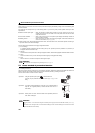
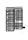
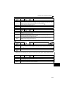
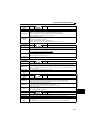
(3) Alarm
When an alarm occurs, the output is not shut off. You can also output an alarm signal by making parameter setting.(Set
"98" in any of Pr. 190 to Pr. 192 (output terminal function selection). Refer to page 144).
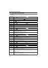
Operation panel
indication
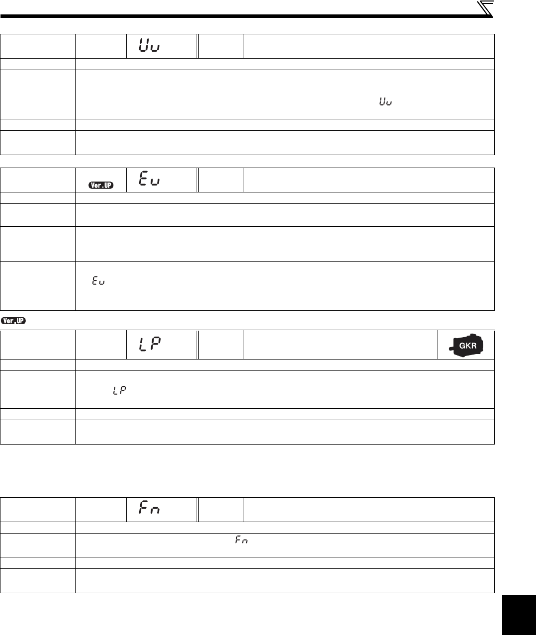
UV FR-PU07 ——
Name
Undervoltage
Description
If the power supply voltage of the drive unit decreases, the control circuit will not perform normal functions. In addition,
the motor torque will be insufficient and/or heat generation will increase. To prevent this, if the power supply voltage
decreases below about 115VAC this function stops the drive unit output and displays .
An alarm is reset when the voltage returns to normal.
Check point
Check that the power supply voltage is normal.
Corrective
action
Check the power supply system equipment such as power supply.
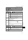
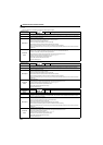
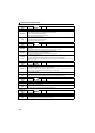
Operation panel
indication
EV
FR-PU07 ——
Name
24V external power supply operation
Description
Flickers while the main circuit power is not supplied and the 24V external power is supplied when FR-E7DS is
mounted.
Check point
Check if the 24V external power is supplied.
Check if the power supply for the drive unit (main circuit) is ON. Check if the power supply voltage is low.
Check if the jumper between terminal P/+ and P1 is removed.
Corrective
action
Turn ON the power supply for the inverter (main circuit).
If appears by turning ON the power supply of the drive unit (main circuit) while the external 24V power is
supplied, check the power supply (for the main circuit).
Check if the jumper is installed securely between terminal P/+ and P1.
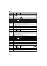
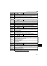
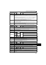
Operation panel
indication
LP
FR-PU07 ——
Name
Stroke limit warning
Description
When the forward rotation stroke end (LSP) or the reverse rotation stroke end (LSN) signal is assigned to an input
terminal, appears when the LSP or LSN signal is turned OFF and remains while the signal is in the OFF state.
(Refer to page 101)
Check point
Check if the LSP or LSN signal is turned OFF.
Corrective
action
Turn ON the LSP or LSN signal.
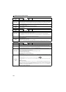
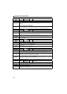
Operation panel
indication
FN FR-PU07 FN
Name
Fan alarm
Description
For the drive unit that contains a cooling fan, appears on the operation panel when the cooling fan stops due to an
alarm or different operation from the setting of Pr. 244 Cooling fan operation selection.
Check point
Check the cooling fan for an alarm.
Corrective
action
Check for fan alarm. Please contact your sales representative.