


72
4.17.1 Operation mode selection (Pr.79)............................................................................................... 186
4.17.2 Operation mode at power-ON (Pr.79, Pr.340)............................................................................ 194
4.17.3 Start command source and speed command source during communication operation (Pr.338,
Pr.339, Pr.550, Pr.551)............................................................................................................... 195
4.18 Communication operation and setting 201
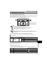
4.18.1 Wiring and configuration of PU connector .................................................................................. 201
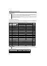
4.18.2 Initial settings and specifications of RS-485 communication
(Pr.117 to Pr.120, Pr.123, Pr.124, Pr.549) ................................................................................. 204
4.18.3 Operation selection at communication error occurrence (Pr.121, Pr.122, Pr.502)..................... 205
4.18.4 Communication EEPROM write selection (Pr.342) .................................................................... 208
4.18.5 Mitsubishi inverter protocol (computer link communication)....................................................... 209
4.18.6 Modbus-RTU communication specifications
(Pr.117, Pr.118, Pr.120, Pr.122, Pr.343, Pr.502, Pr.549) ........................................................... 222
4.18.7 USB communication (Pr. 547, Pr. 548)....................................................................................... 234
4.19 Special operation and speed control 235
4.19.1 PID control (Speed control) (Pr.127 to Pr.134)........................................................................... 235
4.19.2 Regeneration avoidance function (Pr.665, Pr.882, Pr.883, Pr.885, Pr.886)............................... 242
4.20 Useful functions 244
4.20.1 Cooling fan operation selection (Pr. 244) ................................................................................... 244
4.20.2 Display of the life of the drive unit parts (Pr.255 to Pr.259) ........................................................ 245
4.20.3 Maintenance timer alarm (Pr.503, Pr.504).................................................................................. 248
4.20.4 Current average value monitor signal (Pr.555 to Pr.557) ........................................................... 249
4.20.5 Free parameter (Pr.888, Pr.889) ................................................................................................ 251
4.20.6 Initiating a fault (Pr.997).............................................................................................................. 252
4.20.7 Batch setting Mitsubishi HMI (GOT) connection parameters (Pr. 999)....................................... 253
4.21 Setting from the parameter unit and operation panel 255
4.21.1 RUN key rotation direction selection (Pr.40)............................................................................... 255
4.21.2 Setting-dial potentiometer mode/key lock operation selection (Pr.161)...................................... 256
4.21.3 Magnitude of speed change setting (Pr.295).............................................................................. 259
4.21.4 Buzzer control (Pr.990)............................................................................................................... 260
4.21.5 PU contrast adjustment (Pr.991) ................................................................................................ 260
4.22 Parameter clear/ All parameter clear 261
4.23 Initial value change list 262
4.24 Check and clear of the faults history 263