


280
Check first when you have a trouble
5.5 Check first when you have a trouble
5.5.1 Motor does not start
POINT
If the cause is still unknown after every check, it is recommended to initialize the parameters (initial value) then
set the required parameter values and check again.
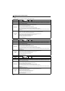
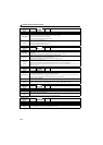
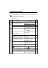
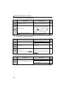
Check
Points
Possible Cause Countermeasures
Refer
to
page
Main
Circuit
Appropriate power supply voltage is not applied.
(Operation panel display is not provided.)
Power ON moulded case circuit breaker (MCCB), an
earth leakage circuit breaker (ELB), or a magnetic
contactor (MC).
Check for the decreased input voltage, input phase loss,
and wiring.
Motor is not connected properly. Check the wiring between the drive unit and the motor. 15
The jumper across P/+ to P1 is disconnected.
Securely fit a jumper across P/+ to P1.
To use a DC reactor (FR-HEL) or Filterpack, remove the
jumper across the terminals P/+ and P1, then connect
the DC reactor or Filterpack.
32
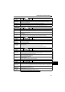
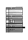
Input
Signal
Start signal is not input.
Check the start command source, and input a start
signal.
PU operation mode:
External operation mode : STF/STR signal
188
Both the forward and reverse rotation start signals (STF,
STR) are input simultaneously.
Turn ON only one of the forward and reverse rotation
start signals (STF or STR).
If the STF and STR signals are turned ON
simultaneously in the initial setting, a stop command is
given.
168
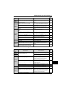
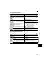
Speed command is zero.
Check the speed command source and enter a speed
command.
188
AU signal is not ON when terminal 4 is used for speed
setting.
Turn ON the AU signal.
Turning ON the AU signal activates terminal 4 input.
168
Output stop signal (MRS) or reset signal (RES) is ON.
(RUN LED on the operation panel flickers while MRS
signal is ON.)
Turn MRS or RES signal OFF.
Drive unit starts the operation with a given start
command and a speed command after turning OFF
MRS or RES signal.
Before turning OFF, ensure the safety.
18
Jumper connector of sink - source is wrongly selected.
Check that the control logic switchover jumper connector
is correctly installed.
If it is not installed correctly, input signal is not
recognized.
21
Voltage/current input switch is not correctly set for
analog input signal (0 to 5V/0 to 10V, 4 to 20mA).
Set Pr.73, Pr.267, and a voltage/current input switch
correctly, then input an analog signal in accordance with
the setting.
18
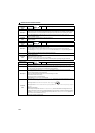
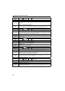
was pressed.
(Operation panel indication is (PS).)
During the External operation mode, check the method
of restarting from a input stop from PU.
270
Two-wire or three-wire type connection is wrong.
Check the connection.
Connect STOP signal when three-wire type is used.
142
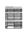
Servo-ON signal (SON) is assigned, but is not input. Turn ON the SON signal. 131
Under position control, servo-ON signal (SON) or pre-
excitation signal (LX) is not input.
Assign the SON signal or the LX signal to an input
terminal, and turn ON the signal.
131
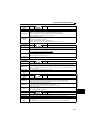
Under position control, position control sudden stop
signal (X87) is input.
Turn OFF the X87 signal.
Check the Pr.535 Position control terminal input selection
setting.
100