


217
Communication operation and setting
4
PARAMETERS
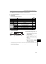
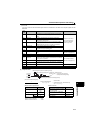
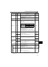
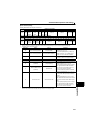
Drive unit reset Write HFD
H9696: resets the drive unit.
As the drive unit is reset at start of communication by the computer, the
drive unit cannot send reply data back to the computer.
4 digits
(A,C/D)
H9966: resets the drive unit.
When data is sent normally, ACK is returned to the computer and then
the drive unit is reset.
4 digits
(A,D)
Faults history
batch clear
Write HF4 H9696: clears the faults history as a batch.
4 digits
(A,C/D)
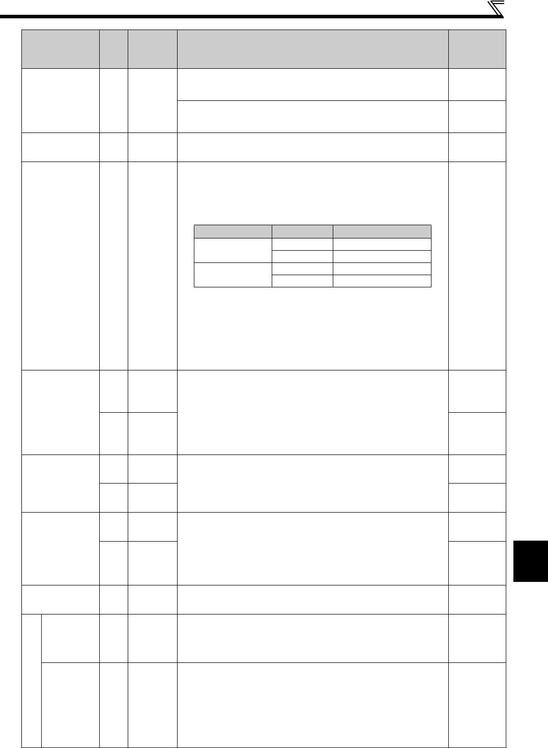
Parameter clear
All clear
Write HFC
All parameters return to the initial values.
Whether to clear communication parameters or not can be selected
according to data.
(: Clear, : Not clear)
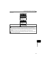
Refer to page 52 for parameter clear, all clear, and communication
parameters.
When clear is executed for H9696 or H9966, communication-related
parameter settings also return to the initial values. When resuming
operation, set the parameters again.
Executing clear will clear the instruction code HEC, HF3, and HFF
settings. In the password locked status, only H9966 and H55AA (all
parameter clear) are valid.
Turning OFF the power supply while clearing parameters with H5A5A or H55AA
also clears the communication parameter settings back to the initial settings.
4 digits
(A,C/D)
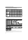
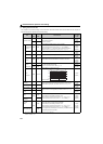
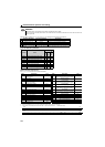
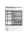
Parameter
Read H00 to H63
Refer to the instruction code (Refer to page 52) and write and/or read
parameter values as required.
When setting Pr.100 and later, link parameter extended setting must be set.
Data format of Pr.37 read and write is E2 and A2
4 digits
(B,E/D)
6 digits
(B,E2/D)
Write H80 to HE3
4 digits
(A,C/D)
6 digits
(A2,C/D)
Link parameter
extended setting
Read H7F
Parameter description is changed according to the H00 to H09 setting.
For details of the settings, refer to the parameter instruction code (Refer to
page 52).
2 digits
(B,E1/D)
Write HFF
2 digits
(A1,C/D)
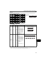
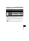
Second parameter
changing
(instruction code
HFF = 1, 9)
Read H6C
Setting calibration parameter (Refer to the list of calibration parameters on
the next page for calibration parameters.)
H00: Speed (The gain speed can also be written using Pr.125 (instruction
code: H99) or Pr.126 (instruction code: H9A).)
H01: Parameter-set analog value
H02: Analog value input from terminal
2 digits
(B,E1/D)
Write HEC
2 digits
(A1,C/D)
Multi command
Write/
Read
HF0
Available for writing 2 commands, and monitoring 2 items for reading data
(Refer to page 221 for detail)
10 digits
(A3,C1/D)
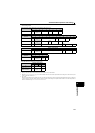
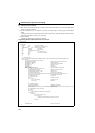
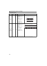
Drive unit type monitor
Drive unit type Read H7C
Reading drive unit type in ASCII code.
"H20" (blank code) is set for blank area
Example of FR-E720EX
H46, H52, H2D, H45, H37, H32, H30, H45, H58, H20 ..H20
20 digits
(B,E3/D)
Capacity Read H7D
Reading drive unit capacity in ASCII code.
Data is read in increments of 0.1kW, and rounds down to 0.01kW
increments
"H20" (blank code) is set for blank area
Example
0.4K.......... " 4"(H20, H20, H20, H20, H20, H34)
0.75K........ " 7"(H20, H20, H20, H20, H20, H37)
6 digits
(B,E2/D)
Item
Read/
Write
Instruction
Code
Data Definition
Number of
Data Digits
(Format)
Refer to page 210 for data format (A, A1, A2, A3, B, C, C1, D, E, E1, E2, E3, F)
The increment is 0.001 and the data format is E2 or A2 when the following conditions are met: Pr.37 = "0.01 to 9998," Pr.144 = "2 to 10," and the
instruction code HFF = "01."
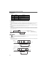
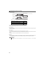
Clear Type Data Communication Pr.
Parameter clear
H9696
H5A5A 1
All parameter clear
H9966
H55AA 1