


I
1 OUTLINE 1
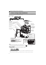
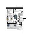
1.1 Product checking and parts identification......................................... 2
1.2 Drive unit and peripheral devices....................................................... 3
1.2.1 Peripheral devices .......................................................................................................................... 5
1.3 Removal and reinstallation of the cover ............................................ 6
1.3.1 Front cover...................................................................................................................................... 6
1.3.2 Wiring cover.................................................................................................................................... 6
1.4 Installation of the drive unit and enclosure design ........................... 7
1.4.1 Drive unit installation environment.................................................................................................. 7
1.4.2 Cooling system types for drive unit panel....................................................................................... 9
1.4.3 Drive unit placement..................................................................................................................... 10
2 WIRING 13
2.1 Wiring ................................................................................................ 14
2.2 Main circuit terminal specifications ................................................ 15
2.2.1 Specification of main circuit terminal ............................................................................................ 15
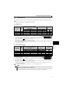
2.2.2 Terminal arrangement of the main circuit terminal, power supply and the motor wiring............... 15
2.2.3 Cables and wiring length .............................................................................................................. 16
2.3 Control circuit specifications........................................................... 18
2.3.1 Control circuit terminal.................................................................................................................. 18
2.3.2 Changing the control logic ............................................................................................................ 21
2.3.3 Wiring of control circuit ................................................................................................................. 23
2.3.4 Connection to the PU connector................................................................................................... 25
2.4 Connection of stand-alone option unit ............................................. 27
2.4.1 Connection of a dedicated external brake resistor (MRS type, MYS type, FR-ABR)
(0.4K or higher)............................................................................................................................. 27
2.4.2 Connection of the brake unit (FR-BU2) ........................................................................................ 29
2.4.3 Connection of the high power factor converter (FR-HC2) ............................................................ 30
2.4.4 Connection of the power regeneration common converter (FR-CV) ............................................ 31
2.4.5 Connection of the DC reactor (FR-HEL)....................................................................................... 32
3 PRECAUTIONS FOR USE OF THE DRIVE UNIT 33
3.1 EMC and leakage currents................................................................ 34
3.1.1 Leakage currents and countermeasures ...................................................................................... 34
3.1.2 EMC measures............................................................................................................................. 36
3.1.3 Power supply harmonics............................................................................................................... 38
CONTENTS