


3
1
OUTLINE
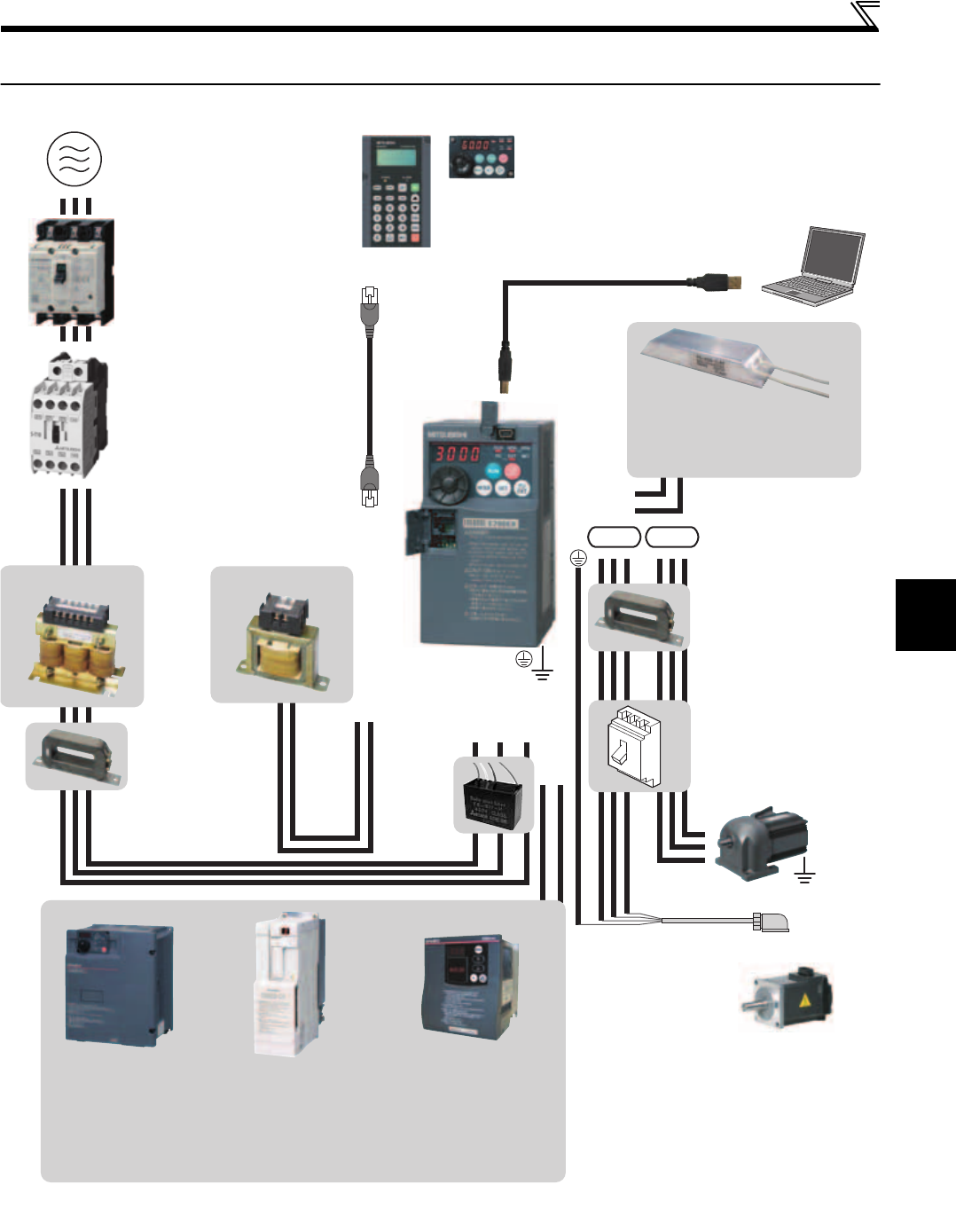
Drive unit and peripheral devices
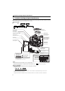
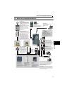
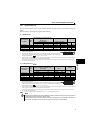
1.2 Drive unit and peripheral devices
Braking capability can be improved. (0.4K or higher)
Always install a thermal relay when using
a brake resistor whose capacity is 11K or higher.
R/L1S/L2T/L3
P1P/+
N/-P/+
UW
P/+
PR
V
Brake resistor
(FR-ABR, MRS type, MYS type)
Noise filter (ferrite core)
(FR-BSF01, FR-BLF)
Install a noise filter (ferrite core)
to reduce the electromagnetic
noise generated from the drive unit.
Effective in the range from about
1MHz to 10MHz. A wire should be
wound four turns at a maximum.
Earth
(Ground)
Earth (Ground)
Devices connected to the output
Do not install a power factor correction capacitor,
surge suppressor or noise filter (capacitor) on the output
side of the drive unit. When installing a moulded case
circuit breaker on the output side of the drive unit,
contact each manufacturer for selection of the
moulded case circuit breaker.
Noise filter (ferrite core) *
(FR-BSF01, FR-BLF)
AC power supply
Use within the permissible power supply
specifications of the drive unit. To ensure
safety, use a moulded case circuit breaker,
earth leakage circuit breaker or magnetic
contactor to switch power ON/OFF.
Magnetic contactor (MC)
Install the magnetic contactor to ensure
safety. Do not use this magnetic contactor
to start and stop the drive unit. Doing so will
cause the drive unit life to be shortened.
Moulded case circuit breaker (MCCB)
or earth leakage circuit breaker
(ELB), fuse
The breaker must be selected carefully
since an inrush current flows in the drive
unit at power on.
Install a noise filter (ferrite core)
to reduce the electromagnetic
noise generated from the drive
unit. Effective in the range from
about 1MHz to 10MHz. When
more wires are passed through,
a more effective result can be
obtained. A wire should be
wound four turns or more.
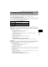
To prevent an electric shock, always earth (ground) the
motor and drive unit. For reduction of induction noise from
the power line of the drive unit, it is recommended to wire
the earthing (grounding) cable by returning it to the earth
(ground) terminal of the drive unit.
AC reactor (FR-HAL)
DC reactor (FR-HEL) *
Noise filter
(capacitor) *
(FR-BIF)
Reduces the
radio noise.
* Filterpack (FR-BFP2), which contains DC reactor and noise filter in one package, is also available.
Parameter unit
(FR-PU07)
By connecting the connection cable
(FR-CB2) to the PU connector,
operation can be performed from
FR-PU07, FR-PA07.
Enclosure surface
operation panel
(FR-PA07)
USB connector
A personal computer and a drive unit
can be connected with a
USB (Ver1. 1) cable.
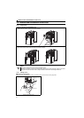
Magnetic motor starter
Example) No-fuse switch
(DSN type)
Install a magnetic motor starter in an
application where the PM motor is
driven by the load even at
power-OFF of the drive unit. Do not
open or close the magnetic motor
starter while the drive unit is running
(outputting)
Reactor (FR-HAL, FR-HEL option)
Reactors (option) must be used when
power harmonics measures are taken,
the power factor is to be improved or the
drive unit is installed near a large power
supply system (500kVA or more). The
drive unit may be damaged if you do not
use reactors. Select the reactor according
to the model. Remove the jumpers across
terminals P/+ and P1 to connect the DC reactor.
Motor (MM-GKR)
The regenerative braking
capability of the drive unit can
be exhibited fully.
Install this as required.
Power supply harmonics
can be greatly suppressed.
Install this as required.
High power factor
converter (FR-HC2)
Power regeneration
common converter
(FR-CV)
Great braking capability
is obtained.
Install this as required.
Brake unit
(FR-BU2)
UWV
Earth
(ground)
S-PM
connection
Motor (S-PM)
MM-GKR
connection
Power supply cable
(Servo motor power supply cable (option))
(Refer to page 302)
(Refer to page 5)
(Refer to page 42)
Drive unit
(FR-E700EX)
(Refer to page 25)
(Refer to page 27)