


30
Connection of stand-alone option unit
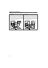
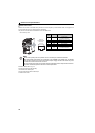
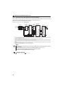
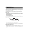
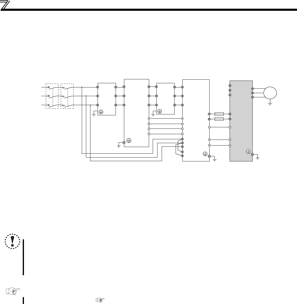
2.4.3 Connection of the high power factor converter (FR-HC2)
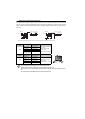
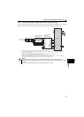
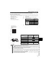
When connecting the high power factor converter (FR-HC2) to suppress power harmonics, perform wiring securely as shown
below. Incorrect connection will damage the high power factor converter and the drive unit.
Perform the wiring securely, and set the following parameter:
Pr.30 Regenerative function selection = "0" (Initial value).
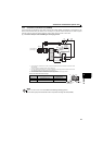
Do not connect anything to power input terminals (R/L1, S/L2, T/L3). Incorrect connection will damage the drive unit.
Do not install an MCCB for the terminals P/+ and N/- (between terminals P and P/+ or between N and N/-). Connecting the opposite polarity of terminals
N/- and P/+ will damage the drive unit.
Assign the X10, RES signal to a terminal using any of Pr.178 to Pr.189 (input terminal function selection). (Refer to page 138)
Always connect the FR-HC2 terminal RDY to a terminal where the X10 or MRS signal is assigned in the drive unit. Always connect the FR-HC2 terminal
SE to the drive unit terminal SD. Not connecting these terminals may damage the FR-HC2.
Always connect the R/L1, S/L2, and T/L3 terminals of FR-HC2 to the power supply. Operating the drive unit without connecting them will damage FR-
HC2.
Do not install an MCCB or MC between the reactor 1 terminals (R/L1, S/L2, T/L3) and FR-HC2 terminals (R4/L14, S4/L24, T4/L34). It will not operate
properly.
Securely perform grounding (earthing) by using the ground (earth) terminal.
Installation of a fuse is recommended. (Refer to the Instruction Manual of FR-HC2.)
NOTE
The voltage phases of terminals R/L1, S/L2, and T/L3 and the voltage phases of terminals R4/L14, S4/L24, and T4/L34
must be matched.
Match the control logic (sink logic / source logic) of the FR-HC2 and the drive unit. (Refer to page 21)
Do not connect a DC reactor (FR-HEL) to the drive unit when FR-HC2 is connected.
A Filterpack cannot be connected when FR-HC2 is connected.
Parameter referred to
Pr.30 Regenerative function selection Refer to page 136
ROH2
ROH1
Outside box
(FR-HCB2)
Drive unit
High power
factor converter
(FR-HC2)
Reactor2
(FR-HCL22)
Motor
M
Reactor1
(FR-HCL21)
P/+P/+
N/-
N/-
X10
SD
RDY
RSO
SE
R/L1
Earth
(ground)
S/L2
T/L3
Three-phase
A
C power
supply
U
V
W
R1/L11
S1/L21
88R
88R
88S
88S
ROH
SD
MCCB
MC
R4/
L14
R4/L14
S4/
L24
S4/L24
T4/
L34
T4/L34
R3/
L13
R3/
L13
S3/
L23
S3/
L23
T3/
L33
T3/
L33
R2/
L12
R2/
L12
S2/
L22
S2/
L22
T2/
L32
T2/
L32
R/
L1
S/
L2
T/
L3
R/L1
S/L2
T/L3
RES
Fuse
∗4
∗3
∗2
∗7
∗7
∗6
∗6
∗5
∗7
∗7
∗6
∗6
∗8
∗1
∗7
∗3