


148
Function assignment of external terminal and control
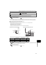
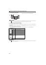
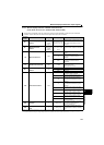
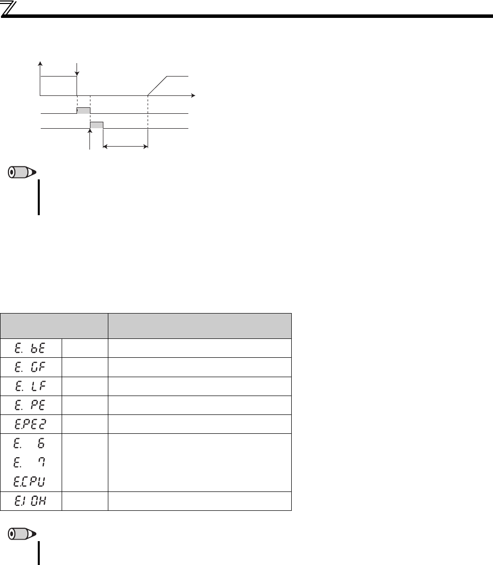
(3) Fault output signal (ALM signal)
(4) Fault output 3 (power-off signal) (Y91 signal)
The Y91 signal is output at occurrence of a fault attributable to the failure of the drive unit circuit or a fault caused by a
wiring mistake.
When using the Y91 signal, set "91 (positive logic)" or "191 (negative logic)" to any of Pr.190 to Pr.192 (output terminal function
selection) to assign the function to the output terminal.
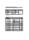
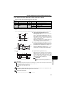
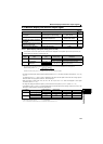
The following table indicates the faults that will output the Y91 signal. (Refer to page 267 for the fault description.)
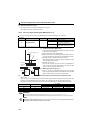
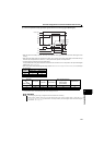
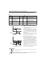
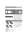
If the drive unit comes to trip, the ALM signal is output.
REMARKS
The ALM signal is assigned to the terminal A, B, C in the default setting. By setting "99 (positive logic) or 199 (negative logic) in
Pr.190 to Pr.192 (output terminal function selection), the ALM signal can be assigned to the other terminal.
Refer to page 268 for the drive unit fault description.
Operation Panel
Indication
Name
E. BE
Brake transistor alarm detection
E.GF
Output side earth (ground) fault overcurrent
E.LF
Output phase loss
E.PE
Parameter storage device fault
E.PE2
Internal board fault
/
/
/
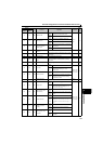
E. 6/
E. 7/
E.CPU
CPU fault
E.IOH
Inrush current limit circuit fault
REMARKS
At occurrence of Output side earth (ground) fault overcurrent, overcurrent trip during acceleration(E.OC1) may be displayed. At
this time, the Y91 signal is output.
ON OFF
ON OFF
Reset ON
Rotation
speed
ALM
RES
Drive unit fault occurrence (Trip)
Time
Reset processing
(about 1s)