


235
Special operation and speed control
4
PARAMETERS
4.19 Special operation and speed control
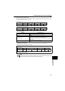
4.19.1 PID control (Speed control) (Pr.127 to Pr.134)
Purpose Parameter to set Refer to page
To perform process control such as
pump and air volume
PID control Pr.127 to Pr.134
235
To avoid overvoltage alarm due to
regeneration by automatic
adjustment of output speed
Regeneration avoidance
function
Pr.882, Pr.883, Pr.885, Pr.886
242
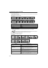
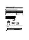
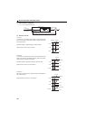
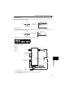
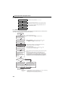
The drive unit can be used to exercise process control, e.g. flow rate, air volume or pressure.
The terminal 2 input signal or parameter setting is used as a set point and the terminal 4 input signal used as a
feedback value to constitute a feedback system for PID control.
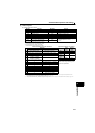
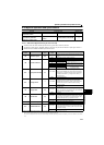
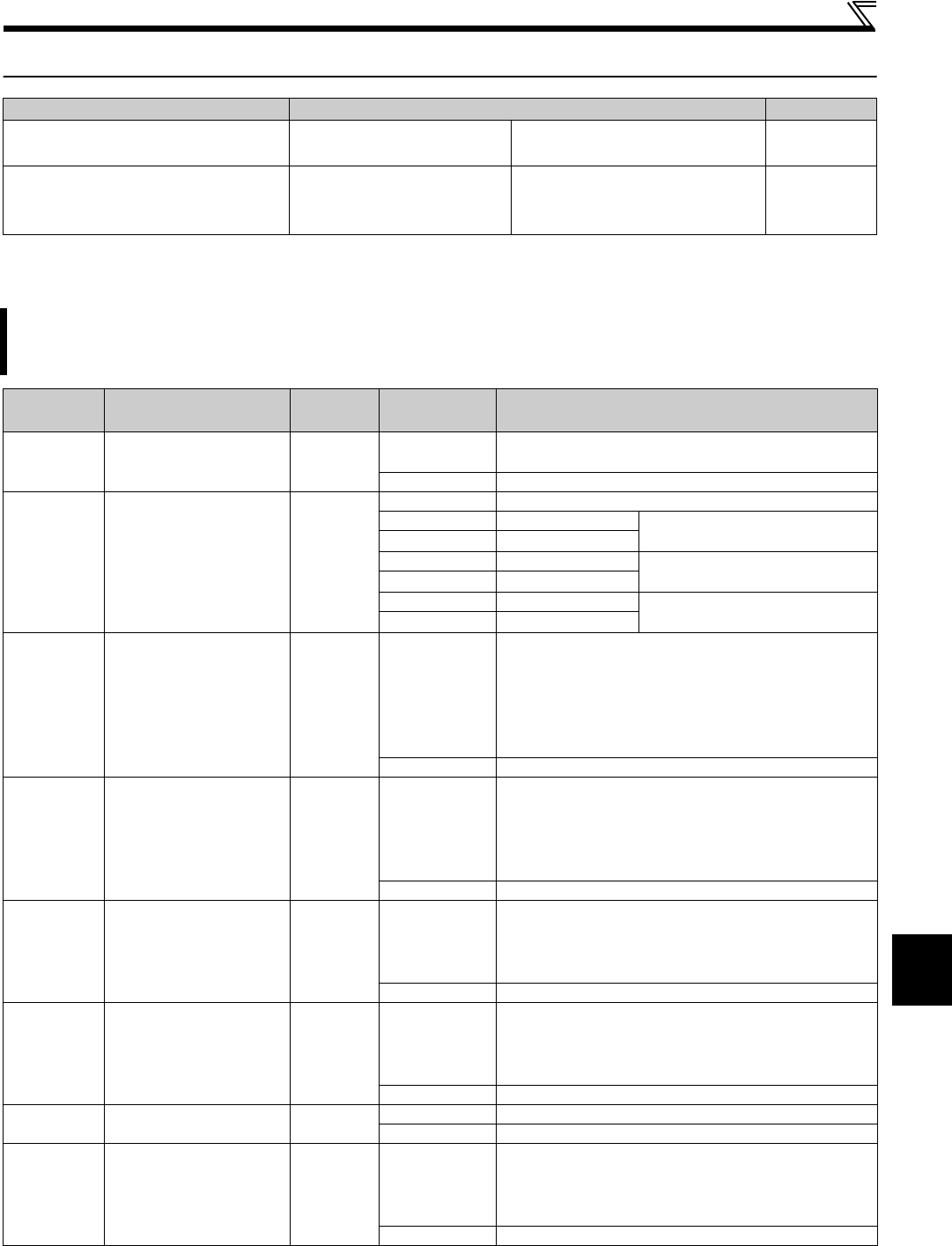
Parameter
number
Name
Initial
value
Setting
range
Description
127
PID control automatic
switchover speed
9999
0 to 4800r/min
Speed at which the control is automatically changed to PID
control.
9999 Without PID automatic switchover function
128 PID action selection
0
0 PID action is not performed
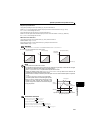
20 PID reverse action Measured value (terminal 4)
Set value (terminal 2 or Pr.133)
21 PID forward action
50 PID reverse action Deviation value signal input (CC-Link
communication)
51 PID forward action
60 PID reverse action Measured value, set point input (CC-
Link communication)
61 PID forward action
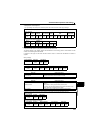
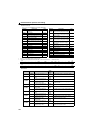
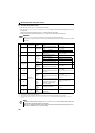
129 PID proportional band
100%
0.1 to 1000%
If the proportional band is narrow (parameter setting is
small), the manipulated variable varies greatly with a slight
change of the measured value. Hence, as the proportional
band narrows, the response sensitivity (gain) improves but
the stability deteriorates, e.g. hunting occurs. Gain Kp= 1/
proportional band
9999 No proportional control
130 PID integral time
1s
0.1 to 3600s
When deviation step is input, time (Ti) is the time required
for integral (I) action to provide the same manipulated
variable as the proportional (P) action. As the integral time
decreases, the set point is reached earlier but hunting
occurs more easily.
9999 No integral control.
131 PID upper limit
9999
0 to 100%
Maximum value
If the feedback value exceeds the setting, the FUP signal is
output. The maximum input (20mA/5V/10V) of the measured
value (terminal 4) is equivalent to 100%.
9999 No function
132 PID lower limit
9999
0 to 100%
Minimum frequency
If the measured value falls below the setting range, the FDN
signal is output. The maximum input (20mA/5V/10V) of the
measured value (terminal 4) is equivalent to 100%.
9999 No function
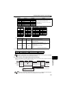
133 PID action set point
9999
0 to 100% Used to set the set point for PID control.
9999 Terminal 2 input is the set point.
134 PID differential time
9999
0 to 100%
For deviation ramp input, time (Td) required for providing
only the manipulated variable for the proportional (P) action.
As the differential time increases, greater response is made
to a deviation change.
9999 No differential control.
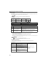
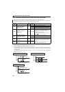
The above parameters can be set when Pr.160 Extended function display selection = "0". (Refer to page 182)
Pr.129, Pr.130, Pr.133 and Pr.134 can be set during operation. These can also be set independently of the operation mode.
When a value exceeding 3000 r/min is set, the rotation speed will be limited at 3000 r/min.
Also, when an S-PM geared motor is used, the maximum setting value differs depending on the drive unit capacity. (0.2 to 2.2K: 12000 r/min, 3.7K: 8000 r/
min)