


29
Connection of stand-alone option unit
2
WIRING
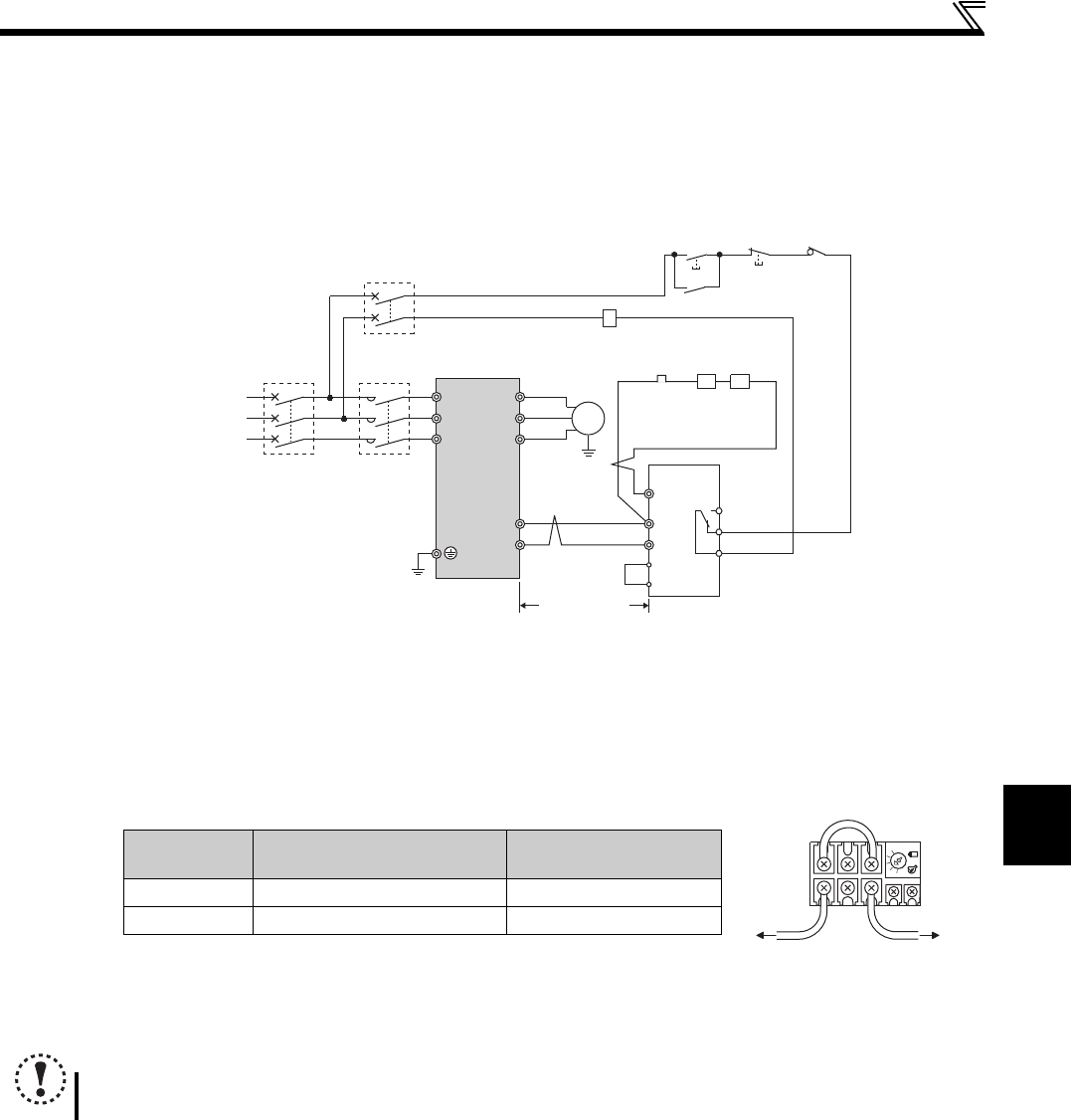
2.4.2 Connection of the brake unit (FR-BU2)
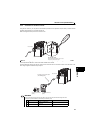
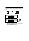
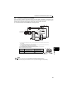
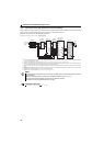
Connect the brake unit (FR-BU2) as shown below to improve the braking capability at deceleration. If the transistors in the
brake unit should become faulty, the resistor can be unusually hot. To prevent unusual overheat and fire, install a magnetic
contactor on the drive unit's input side to configure a circuit so that a current is shut off in case of fault.
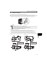
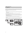
(1) Connection example with the GRZG type discharging resistor
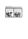
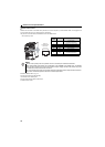
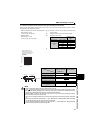
<Recommended external thermal relay>
Connect the drive unit terminals (P/+ and N/-) and brake unit (FR-BU2) terminals so that their terminal names match
with each other.
(Incorrect connection will damage the drive unit and brake unit.)
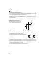
The wiring distance between the drive unit, brake unit (FR-BU2) and discharging resistor should be within 5m. Even
when the wiring is twisted, the cable length must not exceed 10m.
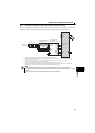
It is recommended to install an external thermal relay to prevent overheat of discharging resistors.
Refer to FR-BU2 manual for connection method of discharging resistor.
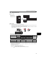
Brake Unit Discharging Resistor
Recommended External
Thermal Relay
FR-BU2-1.5K GZG 300W-50 (one) TH-N20CXHZ 1.3A
FR-BU2-3.7K GRZG 200-10 (three in series) TH-N20CXHZ 3.6A
NOTE
Set "1" in Pr.0 Brake mode selection of the FR-BU2 to use GRZG type discharging resistor.
Do not remove a jumper across terminal P/+ and P1 except when connecting a DC reactor (FR-HEL).
U
V
W
P/+
N/-
R/L1
S/L2
T/L3
Motor
M
Drive unit
PR
N/-
BUE
SD
P/+
A
B
C
FR-BU2
GRZG type
discharging
resistor
RR
Three-phase AC
power supply
MCCB MC
OFFON
MC
10m or less
OCR
MC
External
thermal
relay
OCR
To the brake unit
terminal P/+
To a resisto
r
TH-N20
1/L1 5/L3
2/T1 6/T3