


170
Speed setting by analog input (terminal 2, 4)
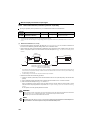
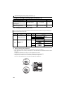
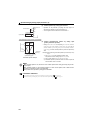
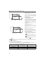
(3) Perform operation by analog input selection
Operation can be performed by inputting the output signal 4 to
20mADC of the adjuster to across the terminals 4-5.
The AU signal must be turned ON to use the terminal 4.
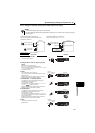
Reversible operation example
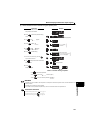
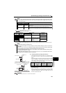
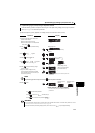
(4) Perform forward/reverse rotation by analog input
(polarity reversible operation)
Setting "10" or "11" in Pr.73 and adjusting Pr.125 (Pr.126) Terminal 2
speed setting gain speed (Terminal 4 speed setting gain speed) and C2
(Pr.902) Terminal 2 speed setting bias speed to C7 (Pr.905) Terminal 4
speed setting gain makes reverse operation by terminal 2 (terminal 4)
valid.
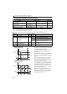
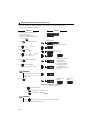
Example) When performing reversible operation by terminal 2 (0 to 5V)
input
1) Set "11" in Pr.73 to make reversible operation valid.
Set speed at maximum analog input in Pr.125 (Pr.903)
2) Set 1/2 of the value set in C4 (Pr.903) in C3 (Pr.902).
3) Reversible operation is performed when 0 to 2.5VDC is input and
forward rotation when 2.5 to 5VDC.
NOTE
When reversible operation is set, be aware of reverse rotation operation when analog input stops (only the start
signal is input).
When reversible operation is valid, reversible operation (0 to 4mA: reverse operation, 4mA to 20mA: forward
operation) is performed by terminal 4 in the initial setting.
Under position control, operation by analog inputs is unavailable.
Parameters referred to
Pr.125 Terminal 2 speed setting gain speed, Pr.126 Terminal 4 speed setting gain speed Refer to page 173
C2(Pr.902) Terminal 2 speed setting bias speed to C7(Pr.905) Terminal 4 speed setting gain Refer to page 173
STF
Drive unit
Forward rotation
Speed setting
SD
4
5
AU
Connection diagram using terminal 4 (4 to 20mADC)
4 to 20mADC
Current input
equipment
2.5V
5V
Reverse
rotation
Forward
rotation
Terminal 2
input (V)
Pr.125
0
C2(Pr.902)
C3(Pr.902) C4(Pr.903)
Speed setting signal
Not
reversible
Reversible
Set speed (r/min)