


5
1
OUTLINE
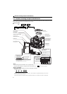
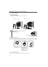
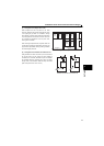
Drive unit and peripheral devices
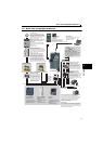
1.2.1 Peripheral devices
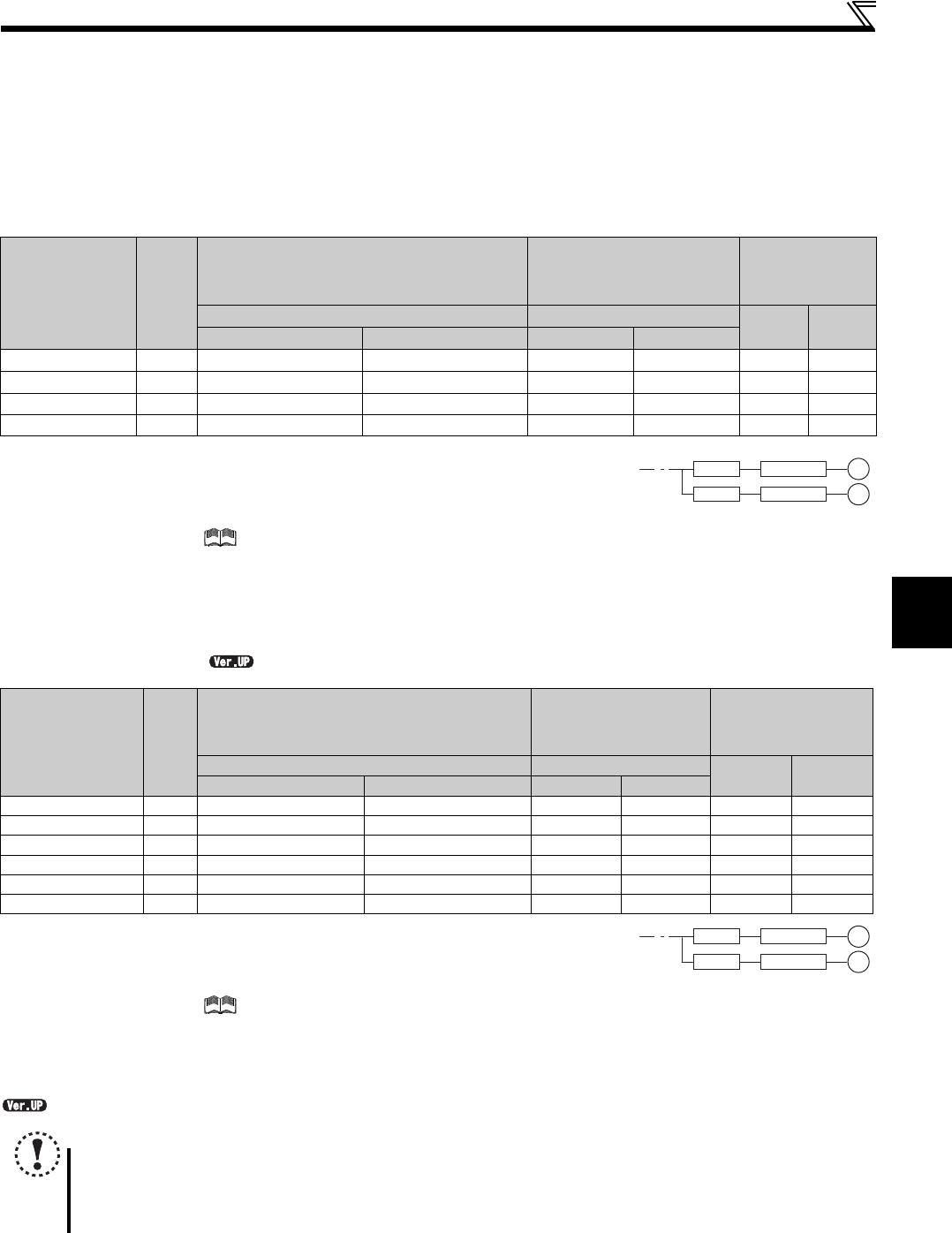
Check the drive unit model of the drive unit you purchased. Appropriate peripheral devices must be selected according to the
capacity.
Refer to the following list and prepare appropriate peripheral devices.
(1) MM-GKR motor
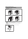
Select an MCCB according to the power supply capacity.
Install one MCCB per drive unit.
For the use in the United States or Canada, select a UL and cUL certified fuse with Class T fuse equivalent cut-
off speed or faster with the appropriate rating for branch circuit protection. Alternatively, select a UL489 molded
case circuit breaker (MCCB). ( Refer to the Instruction Manual (Basic))
Magnetic contactor is selected based on the AC-1 class. The electrical durability of magnetic contactor is 500,000 times. When the magnetic contactor is
used for emergency stop during motor driving, the electrical durability is 25 times.
If using an MC for emergency stop during motor driving, select an MC regarding the drive unit input side current as JEM1038-AC-3 class rated current.
The power factor may be slightly lower.
(2) S-PM geared motor
Select an MCCB according to the power supply capacity.
Install one MCCB per drive unit.
For the use in the United States or Canada, select a UL and cUL certified fuse with Class T fuse equivalent cut-
off speed or faster with the appropriate rating for branch circuit protection. Alternatively, select a UL489 molded
case circuit breaker (MCCB). ( Refer to the Instruction Manual (Basic))
Magnetic contactor is selected based on the AC-1 class. The electrical durability of magnetic contactor is 500,000 times. When the magnetic contactor is
used for emergency stop during motor driving, the electrical durability is 25 times.
If using an MC for emergency stop during motor driving, select an MC regarding the drive unit input side current as JEM1038-AC-3 class rated current.
The power factor may be slightly lower.
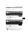
.......Specifications differ according to the date assembled. Refer to page 316 to check the SERIAL number.
Applicable drive
unit Model
Motor
Output
(kW)
Moulded Case Circuit Breaker (MCCB)
or Earth Leakage Circuit Breaker (ELB)
(NF, NV type)
Magnetic Contactor (MC) Reactor
Reactor connection Reactor connection
FR-HAL FR-HEL
without with without with
FR-E720EX-0.1K 0.1 5A 5A S-T10 S-T10 0.4K
0.4K
FR-E720EX-0.2K 0.2 5A 5A S-T10 S-T10
0.4K
0.4K
FR-E720EX-0.4K 0.4 5A 5A S-T10 S-T10 0.4K 0.4K
FR-E720EX-0.75K 0.75 10A 10A S-T10 S-T10 0.75K 0.75K
Applicable drive
unit Model
Motor
Output
(kW)
Moulded Case Circuit Breaker (MCCB)
or Earth Leakage Circuit Breaker (ELB)
(NF, NV type)
Magnetic Contactor
(MC)
Reactor
Reactor connection Reactor connection
FR-HAL FR-HEL
without with without with
FR-E720EX-0.2K 0.1 5A 5A S-T10 S-T10 0.4K 0.4K
FR-E720EX-0.4K 0.2 5A 5A S-T10 S-T10 0.4K 0.4K
FR-E720EX-0.75K 0.4 10A 5A S-T10 S-T10 0.4K 0.4K
FR-E720EX-1.5K 0.75 15A 10A S-T10 S-T10 0.75K 0.75K
FR-E720EX-2.2K 1.5 20A 15A S-T10 S-T10 1.5K 1.5K
FR-E720EX-3.7K 2.2 30A 30A S-T21 S-T10 2.2K 2.2K
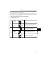
NOTE
When using the S-PM geared motor, select an MCCB and a magnetic contactor according to the drive unit model, and
select cables and reactors according to the motor output.
When the breaker on the drive unit input side trips, check for the wiring fault (short circuit), damage to internal parts of
the drive unit, etc. Identify the cause of the trip, then remove the cause and power ON the breaker.
MCCB Drive unit
MCCB Drive unit
M
M
MCCB Drive unit
MCCB Drive unit
M
M