


87
4
PARAMETERS
Speed control
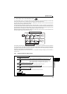
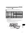
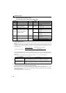
4.4.8 Adjusting the motor wiring resistance (Pr.658)
.......Specifications differ according to the date assembled. Refer to page 316 to check the SERIAL number.
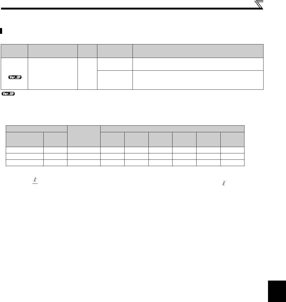
The motor wiring resistance can be set. The set value is calculated according to the following formula.
Wiring resistance = Resistance per 1 m () Wiring length (m)
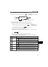
Reference value
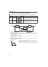
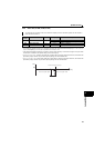
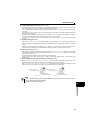
For special size cables, the value is calculated according to the following formula.
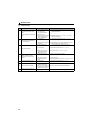
Adjust if acceleration/deceleration characteristics are unstable. In normal condition, setting is not required.
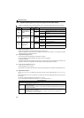
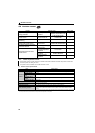
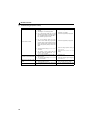
Parameter
number
Name
Initial
value
Setting range Description
658
Wiring resistance
9999
0 to 5
Set the motor wiring resistance. PM sensorless vector control is
performed with the set resistance value.
9999
The motor wiring resistance calculated by the drive unit is set. PM
sensorless vector control is performed with the calculated
resistance value.
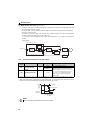
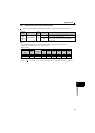
Cable size
Resistance
per 1 m ()
Resistance in the wiring length ()
HIV cables, etc.
(mm
2
)
AWG 1 m 2 m 5 m 10 m 20 m 30 m
0.75 19 0.029100 0.029 0.058 0.146 0.291 0.582 0.873
0.75 18 0.021800 0.022 0.044 0.109 0.218 0.436 0.654
2 14 0.008573 0.009 0.017 0.043 0.086 0.171 0.257
R()=
(: constant 1.7241 10
-2
(mm
2
/m) (copper wire), A: cross section area (mm
2
), : length (m))
A