


191
Selection of operation mode and operation location
4
PARAMETERS
(9) PU operation interlock (setting "7")
The PU operation interlock function is designed to forcibly change the operation mode to the External operation mode
when the PU operation interlock signal (X12) input turns OFF.
This function prevents the drive unit from being inoperative by the external command if the mode is accidentally left
unswitched from PU operation mode.
Set "7" (PU operation interlock) in Pr.79.
For the terminal used for X12 signal (PU operation interlock signal) input, set "12" to any of Pr.178 to Pr.184 (input terminal
function selection) to assign the function. (Refer to page 138 for Pr.178 to Pr.184.)
When the X12 signal is not assigned, function of the MRS signal switches from MRS (output stop) to PU operation
interlock signal.
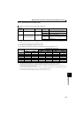
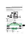
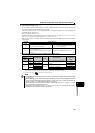
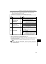
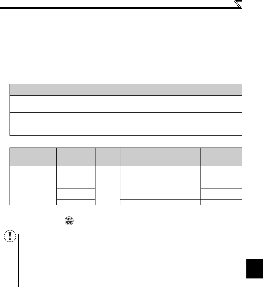
<Function/operation changed by switching ON-OFF the X12 (MRS) signal>
X12 (MRS)
Signal
Function/Operation
Operation Mode Parameter Write
ON
Operation mode (External, PU, NET) switching enabled
Output stop during External operation
Parameter write enabled (depending on Pr.77 Parameter
write selection and each parameter write conditions (Refer
to page 52 for the parameter list))
OFF
Forcibly switched to External operation mode
External operation allowed
Switching between the PU and NET operation mode is
enabled
Parameter write disabled with exception of Pr.79
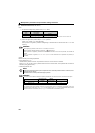
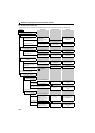
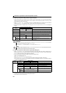
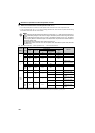
Operating Condition
X12 (MRS) Signal
Operation
Mode
Operating Status
Switching to PU,
NET Operation
Mode
Operation
Mode
Status
PU/NET
During
stop
ON OFF
External
If external operation speed setting and start
signal are entered, operation is performed in
that status.
Disallowed
Running ON OFF Disallowed
External
During
stop
OFF ON
External
During stop
Allowed
ON OFF Disallowed
Running
OFF ON During operation output stop Disallowed
ON OFF Output stop operation Disallowed
The operation mode switches to the External operation mode independently of whether the start signal (STF, STR) is ON or OFF. Therefore, the
motor is run in External operation mode when the X12 (MRS) signal is turned OFF with either of STF and STR ON.
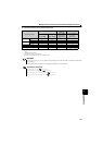
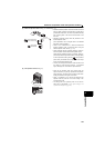
At fault occurrence, pressing
of the operation panel resets the drive unit.
NOTE
If the X12 (MRS) signal is ON, the operation mode cannot be switched to the PU operation mode when the start signal
(STF, STR) is ON.
When the MRS signal is used as the PU interlock signal, the MRS signal serves as the normal MRS function (output
stop) by turning ON the MRS signal and then changing the Pr.79 value to other than "7" in the PU operation mode. As
soon as "7" is set to Pr.79 , the MRS signal acts as the PU interlock signal.
When the MRS signal is used as the PU interlock signal, the logic of the signal is as set in Pr.17. When Pr.17 = "2", read
ON as OFF and OFF as ON in the above explanation.
Changing the terminal assignment using Pr.178 to Pr.184 (input terminal function selection) may affect the other functions.
Set parameters after confirming the function of each terminal.