


135
Motor brake and stop operation
4
PARAMETERS
4.11.2 Activating the electromagnetic brake (MBR signal, Pr.736)
The above parameter can be set when Pr.160 Extended function display selection = "0". (Refer to page 182)
Interlock can be provided for the electromagnetic brake operation by setting a delay from output of the electromagnetic
brake interlock signal (MBR) to start of the actual operation in Pr.736 Electromagnetic brake interlock time.
The interlock time set in Pr.736 is enabled even if the MBR signal is not assigned. Set Pr.736 = "0" if the interlock time
setting is not required.
For the terminal used for MBR signal output, assign the function by setting "21 (positive logic)" or "121 (negative logic)" in
any of Pr.190 to Pr.192 (output terminal function selection).
Additionally configure an external circuit, which can also command an emergency stop to the electromagnetic brake.
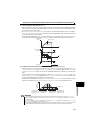
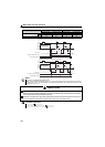
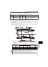
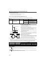
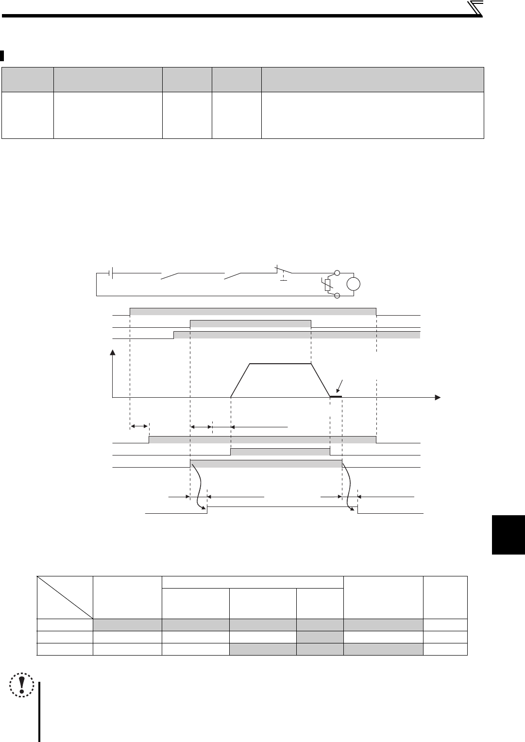
Use the electromagnetic brake interlock signal (MBR) to activate the electromagnetic brake.
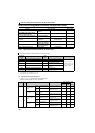
Parameter
number
Name
Initial
value
Setting
range
Description
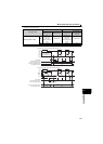
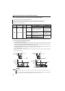
736
Electromagnetic brake
interlock time
0s 0 to 1s
Set the waiting time to start the first magnetic pole detection
after drive unit startup and the MBR signal output.
Set the open delay time (including relay operation delay) of the
electromagnetic brake or longer.
NOTE
Changing the terminal assignment using Pr.190 to Pr.192 (output terminal function selection) may affect the other
functions. Set parameters after confirming the function of each terminal. (Refer to page 138)
The MBR signal is not activated while the main circuit capacitor life is being measured. (Refer to page 245)
The motor generates no torque while the electromagnetic brake is open before drive unit operation, or after zero
speed control or DC injection brake operation. Thus, the motor may be rotated by an external force. Check that no
drop or other accidents will occur in an application like a lift, where the motor rotates while the brake is opened.
Rotation
speed
Reset
processing
ON
ON
ON
STF
Power
supply
RH
ON
RY
RUN
ON
Pr.736
MBR
ON
Open delay time
+ external relay, etc. ∗1
Brake delay time
+ external relay, etc. ∗2
Electromagnetic brake
interlock (MBR)
Power supply for
electromagnetic brake
Fault output
(ALM)
Emergency stop
B
Electromagnetic
brake
Time
Electromagnetic brake operation
Operation Operation
Open
Zero speed control,
servo lock, or
DC injection brake ∗3
(r/min)
Initial magnetic pole detection
(Approx. 100ms)
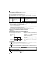
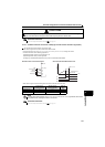
The release of the electromagnetic brake is delayed for the electromagnetic brake release time and the operation time of the relays, etc. in
external circuits.
The operation of the electromagnetic brake is delayed for the electromagnetic brake delay time and the operation time of the relays, etc. in
external circuits.
When the drive unit is set as Pr.10 = "0r/min" and Pr.11 = "0.0s", the outputs are shut off when the speed reaches 0r/min during deceleration,
and the motor starts coasting.
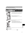
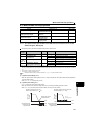
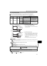
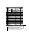
During a fault occurrence, or while the MRS signal is ON
Start signal OFF
(during a stop)
Start signal ON During zero speed
control,
servo lock or
DC injection brake
Output
shutoff
During a stop
(no speed
setting)
During a stop
(with a speed
setting)
Running
RY
ON ON ON ON ON OFF
RUN
OFF OFF OFF ON OFF OFF
MBR
OFF OFF ON ON ON OFF
Drive unit
status
Output
signal