


308
Specifications of the dedicated PM motor [MM-GKR motor]
X indicates the direction of the motor's output shaft, and Y indicates the direction vertical to the motor's output shaft. Usually, the indicated value is of the
non-load side bracket where the vibration is the greatest.
Bearing is subject to fretting while the motor is stopped. Suppress the vibration to about the half of the permissible value.
The standard motor may not be used under the condition where it is constantly exposed to oil mist, oil, or water. For the details, please contact your sales
representative.
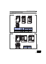
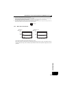
"V10" means that the vibration amplitude of the single motor is 10m or lower. The following figure shows the installation orientation of the motor and
measurement position at the vibration degree measurement.
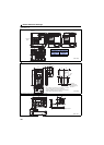
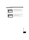
For the permissible load on the shaft, refer to the following figure. On the shaft, do not apply a load exceeding the value in the table.
Each value in the table shows the permissible value for the single load application.
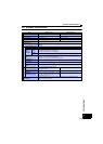
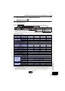
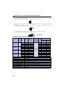
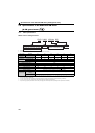
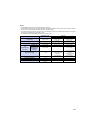
Reduction gear equipped model specifications
Reduction gear equipped model for general industrial machines: G0
Model
Output
(W)
Reduction
ratio
Actual
reduction
ratio
Moment of
inertia J
(
10
-4
kg·m
2
)
Permissible
load inertia
moment ratio
(calculation at
motor shaft)
Mass
(kg)
Permissible load on the
shaft
Permissible
radial load
(N)
Permissible
thrust load
(N)
MM-GKR13G0 100
1/5 42/221 0.0720
10 times or lower
of the moment of
motor inertia
1.3 150 200
1/12 9/104 0.0706 1.3 240 320
1/20 12/247 0.0703 1.3 370 450
1/30 24/713 0.0768 2.4 500 500
MM-GKR23G0 200
1/5 44/217 0.222 2.8 330 350
1/12 48/589 0.204 2.8 710 720
1/20 32/651 0.201 2.8 780 780
1/30 24/713 0.200 2.8 780 780
MM-GKR43G0 400
1/5 15/77 0.406 3.2 330 350
1/12 9/110 0.390 3.2 710 720
1/20 9/189 0.399 4.3 760 780
1/30 12/351 0.398 4.3 760 780
MM-GKR73G0 750
1/5 19/95 1.37 5.5 430 430
1/12 40/475 1.32 5.5 620 620
1/20 14/285 1.29 7.3 970 960
1/30 25/722 1.28 7.3 970 980
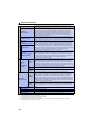
Item Specifications
Installation method
Flange mounting
Installation orientation
Any orientation
Lubrication method
Grease (already filled)
Rotation direction of output axis
Same as that of the motor output axis
Backlash
60 minutes or less at the output shaft of the reduction gear
Maximum torque
Twice of the rated torque (For the rated torque, refer to page 307)
Permissible speed (motor axis)
3000r/min (Instantaneous permissible speed: 3450r/min)
IP rating
Equivalent to IP44
Vibration resistance
X: 29.4 m/s
2
, Y: 29.4 m/s
2
Reduction gear efficiency
80% or higher
Motor
XY
Top
Bottom
Measurement
position
Motor
L
Radial load
Thrust load
L: Distance from the flange
mounting surface to the
center of the load