


15
2
WIRING
Main circuit terminal specifications
2.2 Main circuit terminal specifications
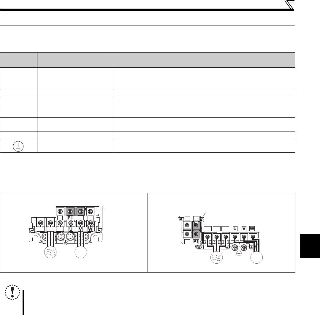
2.2.1 Specification of main circuit terminal
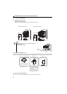
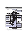
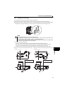
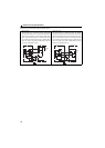
2.2.2 Terminal arrangement of the main circuit terminal, power supply and the motor
wiring
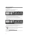
Three-phase 200V class
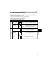
Terminal
Symbol
Terminal Name Description
R/L1,
S/L2,
T/L3
AC power input
Connect to the commercial power supply.
Keep these terminals open when using the high power factor converter (FR-HC2) or
power regeneration common converter (FR-CV).
U, V, W Drive unit output Connect a three-phase squirrel-cage motor.
P/+, PR Brake resistor connection
Connect a brake resistor (FR-ABR, MRS type, MYS type) across terminals P/+ and
PR.
(The brake resistor can not be connected to the 0.1K or 0.2K.)
P/+, N/- Brake unit connection
Connect the brake unit (FR-BU2), power regeneration common converter (FR-CV)
or high power factor converter (FR-HC2).
P/+, P1 DC reactor connection Remove the jumper across terminals P/+ and P1 and connect a DC reactor.
Earth (Ground) For earthing (grounding) the drive unit chassis. Must be earthed (grounded).
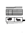
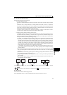
FR-E720EX-0.1K to 0.75K FR-E720EX-1.5K to 3.7K
NOTE
Make sure the power cables are connected to the R/L1, S/L2, T/L3. (Phase need not be matched.) Never connect the
power cable to the U, V, W of the drive unit. Doing so will damage the drive unit.
Connect the motor to U, V, W. Turning ON the forward rotation switch (signal) at this time rotates the motor
counterclockwise when viewed from the load shaft.
MotorPower supply
N/-
P/+ PR
M
R/L1 S/L2 T/L3
Jumpe
r
N/-
P/+
PR
M
R/L1 S/L2 T/L3
Motor
Power supply
Jumper