


Introduction
33
ProSecure Unified Threat Management (UTM) Appliance
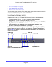
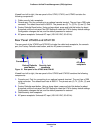
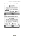
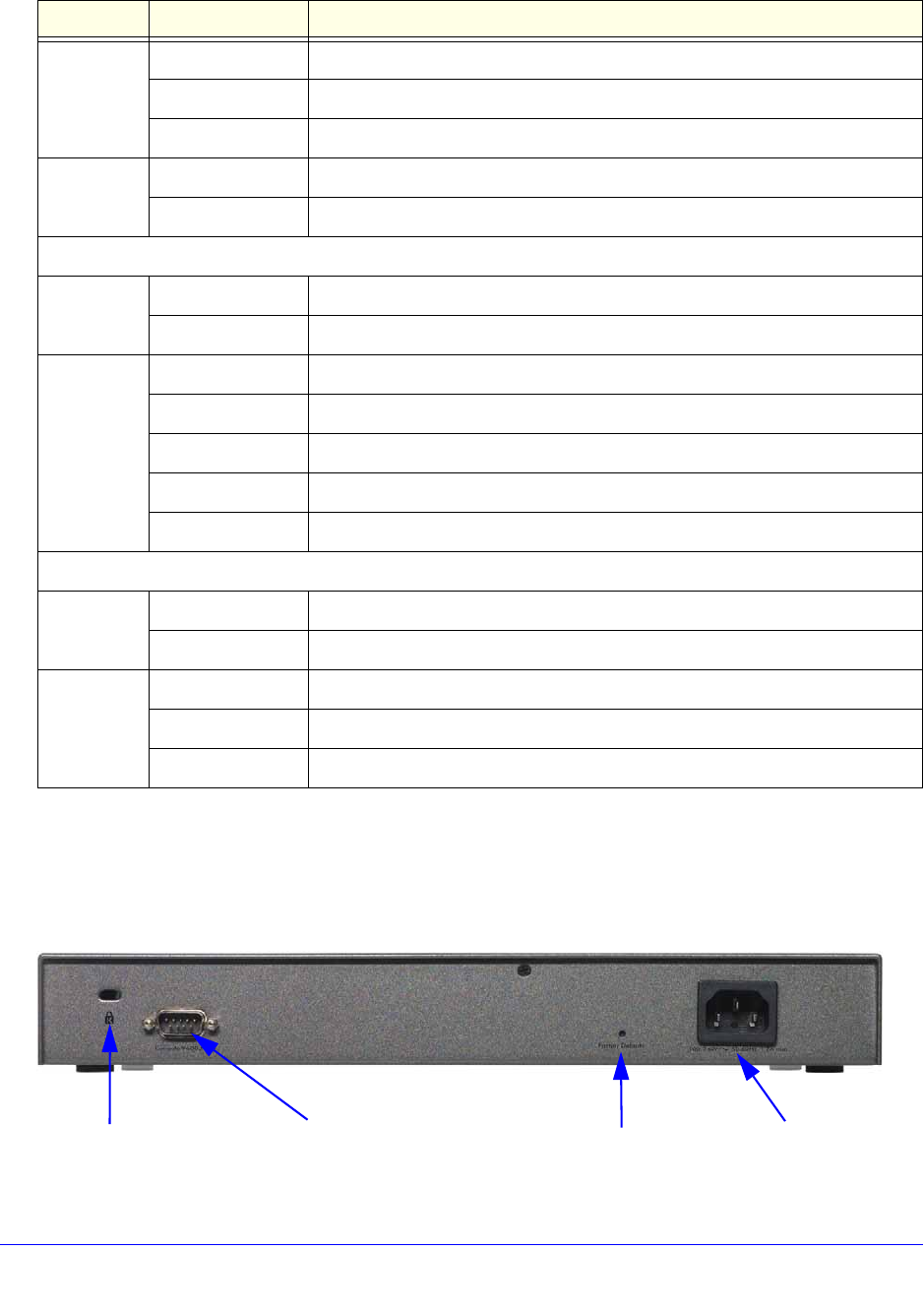
Rear Panel UTM5, UTM10, and UTM25
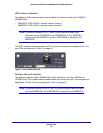
The rear panel of the UTM5, UTM10, and UTM25 includes the cable lock receptacle, the
console port, the Factory Defaults reset button, and the AC power connection.
Figure 9. Rear panel of the UTM5, UTM10, and UTM25
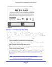
Right LED Off The WAN port is operating at 10 Mbps.
On (amber) The WAN port is operating at 100 Mbps.
On (green) The WAN port is operating at 1000 Mbps.
Active LED Off The WAN port either is not enabled or has no link to the Internet.
On (green) The WAN port has a valid Internet connection.
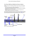
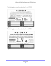
Wireless network module
Module
Status LED
Off The module is not enabled.
On (green) The module is enabled.
Wireless
Link LED
Off The wireless access point is not enabled.
On (green) The wireless access point is enabled in 2.4-GHz operating mode.
Blinking (green) There is wireless activity in 2.4-GHz operating mode.
On (yellow) The wireless access point is enabled in 5-GHz operating mode.
Blinking (yellow) There is wireless activity in 5-GHz operating mode.
xDSL network modules
Module
Status LED
Off The module is enabled or has a link to the telephone line.
On (green) The module either is not enabled or has no link to the telephone line.
Link LED Off The xDSL port has no Internet connection.
On (green) The xDSL port functions in ADSL mode.
On (yellow) The xDSL port functions in VDSL mode.
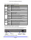
Table 3. LED descriptions UTM9S and UTM25S (continued)
LED Activity Description
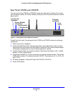
Security lock
receptacle
Console port
Factory Defaults
AC power
receptacle
reset button