


CONTENTS
1. Installation
1-1 Installation of servomotor..................................................................................................... 1-2
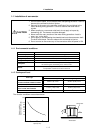
1-1-1 Environmental conditions .............................................................................................. 1-2
1-1-2 Quakeproof level............................................................................................................ 1-2
1-1-3 Cautions for mounting load (prevention of impact on shaft) ......................................... 1-3
1-1-4 Installation direction ....................................................................................................... 1-3
1-1-5 Shaft characteristics ...................................................................................................... 1-4
1-1-6 Oil/water standards........................................................................................................ 1-5
1-1-7 Cable stress ................................................................................................................... 1-7
1-2 Installation of spindle motor ................................................................................................. 1-8
1-2-1 Environmental conditions .............................................................................................. 1-8
1-2-2 Shaft characteristics ...................................................................................................... 1-9
1-3 Installation of the control unit ............................................................................................. 1-10
1-3-1 Environmental conditions ............................................................................................ 1-10
1-3-2 Installation direction and clearance............................................................................. 1-11
1-3-3 Prevention of entering of foreign matter...................................................................... 1-11
1-3-4 Panel installation hole work drawings (Panel cut drawings)....................................... 1-12
1-3-5 Heating value............................................................................................................... 1-13
1-3-6 Heat radiation countermeasures ................................................................................. 1-14
1-4 Installing the spindle detector ............................................................................................ 1-16
1-4-1 Magnetic sensor .......................................................................................................... 1-16
1-4-2 Spindle end detector.................................................................................................... 1-18
1-4-3 Spindle end PLG.......................................................................................................... 1-19
1-5 Noise measures................................................................................................................. 1-22
2. Wiring and Connection
2-1 Part system connection diagram ......................................................................................... 2-3
2-2 Main circuit terminal block/control circuit connector............................................................ 2-4
2-2-1 Names and applications of main circuit terminal block signals and control circuit
connectors ..................................................................................................................... 2-4
2-2-2 Connector pin assignment............................................................................................. 2-5
2-3 NC and drive unit connection ......................................................................................................... 2-8
2-4 Motor and detector connection..................................................................................................... 2-11
2-4-1 Connecting the servomotor ......................................................................................... 2-11
2-4-2 Connecting the full-closed loop system....................................................................... 2-18
2-4-3 Connecting the synchronous control system .............................................................. 2-22
2-4-4 Connection of the spindle motor.................................................................................. 2-28
2-5 Connection of power supply .............................................................................................. 2-33
2-5-1 Power supply input connection ...................................................................................... 2-34
2-5-2 Connecting the grounding cable.................................................................................. 2-37
2-5-3 Main circuit control ......................................................................................................... 2-38
2-6 Wiring of the motor brake .................................................................................................. 2-39
2-6-1 Wiring of the motor magnetic brake ............................................................................ 2-39
2-6-2 Dynamic brake unit wiring ........................................................................................... 2-41
2-7 Peripheral control wiring....................................................................................................... 2-42
2-7-1 Input/output circuit wiring ............................................................................................... 2-42
2-7-2 Spindle coil changeover .............................................................................................. 2-43
2-7-3 Wiring of an external emergency stop......................................................................... 2-46