1. Installation
1 - 17
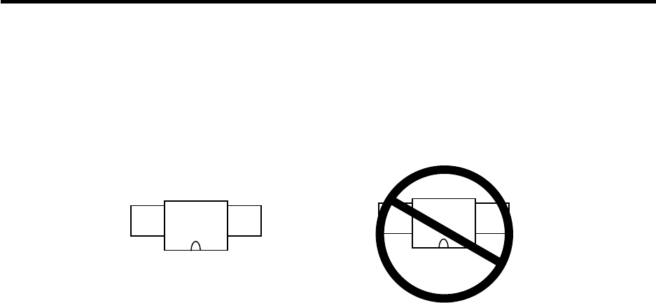
(3) Magnet and sensor installation directions
• Install so that the magnet's reference hole and sensor's reference notch are aligned.
(Standard/high-speed standards)
• Install so that the magnet's N pole comes to the left side when the sensor's reference notch is
faced downward. (High-speed compact/high-speed ring)
(4) Cautions
[1] Do not apply impacts on the magnet. Do not install strong magnets near the magnet.
[2] Sufficiently clean the surrounding area so that iron chips and cutting chips do not adhere to the
magnet. Demagnetize the round disk before installing.
[3] Securely install the magnet onto the spindle with an M4 screw. Take measures to prevent
screw loosening as required.
[4] Balance the entire spindle rotation with the magnet installed.
[5] Install a magnet that matches the spindle's rotation speed.
[6] When installing the magnet onto a rotating body's plane, set the speed to 6,000r/min or less.
[7] Install so that the center line at the end of the head matches the center of the magnet.
[8] The BKO-C1730 is not an oil-proof product. Make sure that oil does not come in contact with
BNO-C1730 or BKO-C1810.
[9] When connecting to the spindle drive unit, wire so that the effect of noise is suppressed.
N S
|
Reference notch
Sensor
Magnet
S N
|
Reference notch
Sensor
Magnet


