


3. Setup
3 - 82
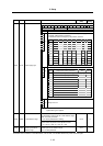
No. Abbr. Parameter name Details
Setting range
(Unit)
Standard
setting
F E D C B A 9 8 7 6 5 4 3 2 1 0
amp rtyp ptyp
bit Explanation
0
1
2
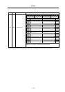
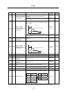
When the CN4 connector of the drive unit and the power supply are
connected, setting below is necessary.
To validate the external emergency stop function, add 40h.
3
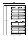
Setting 0x 1x 2x 3x 4x 5x 6x 7x 8x
4
x0 Not used CV-300
5
x1 CV-110 CR-10
6
x2 CV-220 CR-15
7
ptyp
x3 CR-22
x4 CV-37 CR-37
x5 CV-150
MDS-B-
CVE-450
MDS-B-
CVE-550
x6 CV-55 CV-260 CR-55
x7 CV-370
x8 CV-75 CR-75
x9 CV-185 CR-90
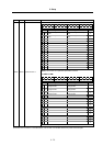
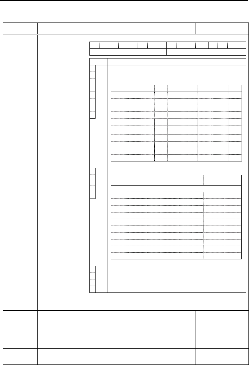
SP041 PTYP* Power supply type
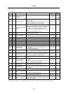
8
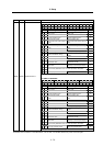
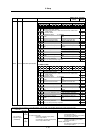
Set the regenerative resistor type when MDS-A-CR is used.
9 Setting Regenerative resistor model name
Resistance
value
Capacity
A0
MDS-C1-CV (Setting when using power supply regeneration)
B
rtyp
1
GZG200W260HMJ (Note)
26Ω
80W
2
GZG300W130HMJ×2
26Ω
150W
3
MR-RB30
13Ω
300W
4
MR-RB50
13Ω
500W
5
GZG200W200HMJ×3
6.7Ω
350W
6
GZG300W200HMJ×3
6.7Ω
500W
7
R-UNIT-1
30Ω
700W
8
R-UNIT-2
15Ω
700W
9
R-UNIT-3
15Ω
2100W
A~F
No setting
C
D
E
F
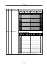
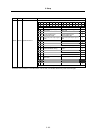
amp
Always set to "0".
(Note) When MDS-B-SP-370, 450 or 550 is used, set "0" even if power
regeneration type is applied.
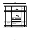
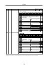
<For MDS-C1-SP/SPH/SPM>
This parameter is used to set the C-axis detector range.
Set "0" for this parameter.
"2" is used by Mitsubishi for testing.
SP042 CRNG* C-axis detector range
<For MDS-C1-SPX/SPHX>
Set the number of pulses for the spindle end PLG.
"4" = 128, "5" = 256, "6" = 512, "8" = 180
0 to 8 0
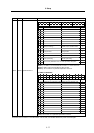
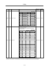
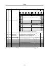
SP043 TRNG*
Synchronous tapping,
spindle synchronous
detector range
This parameter is used to set the synchronous tapping or
spindle synchronous detector range.
Set "0" for this parameter.
0 to 7 0
Parameters with an asterisk * in the abbreviation, such as OSP*, are validated with the NC power turned ON again.