Appendix 1. Cable and Connector Specifications
A1 - 9
(3) Spindle detector cable
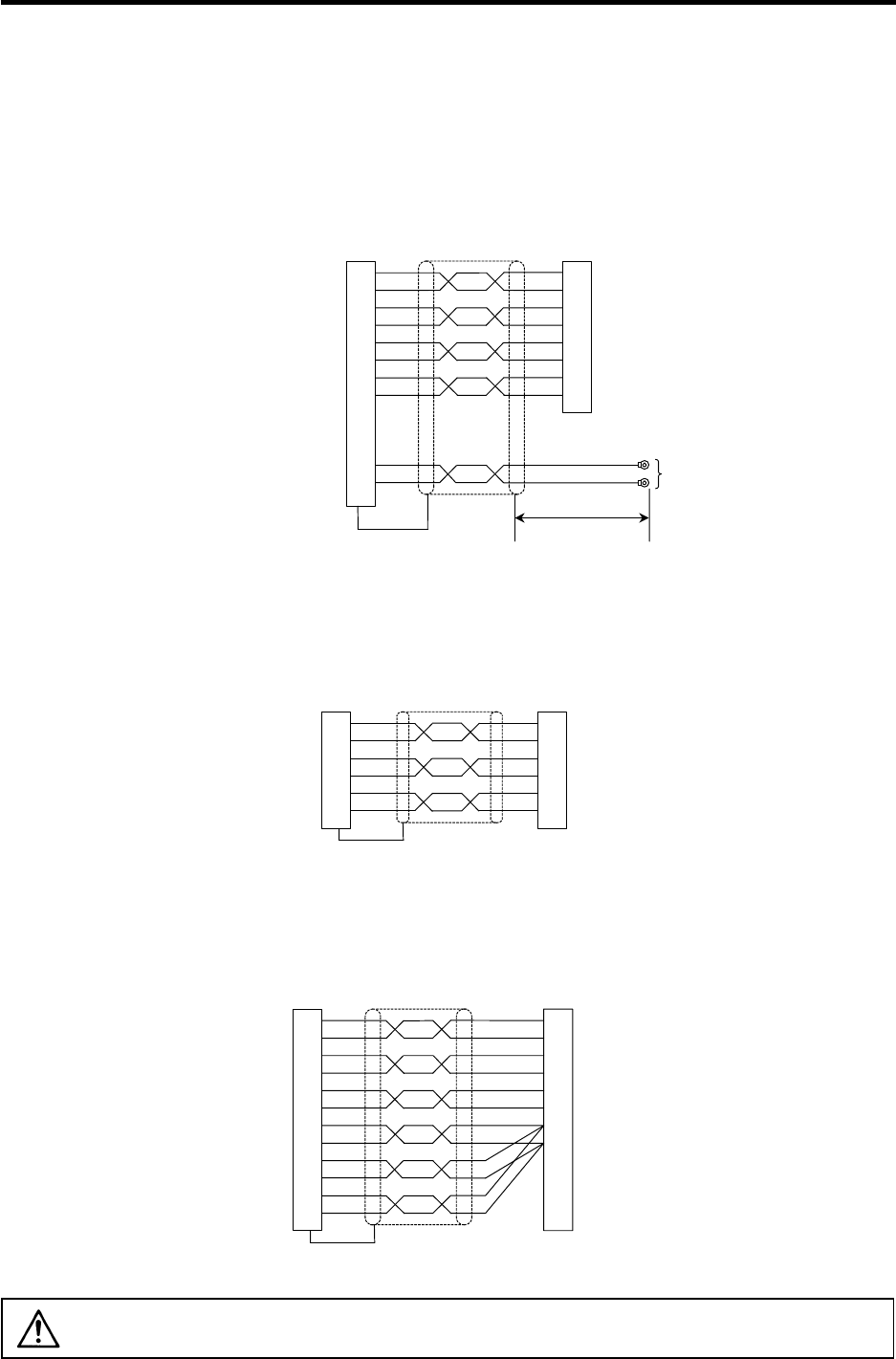
<CNP5 cable connection diagram>
6
16
7
17
8
5
15
1
3
13
P
A
R
A
PB
RB
PZ
P15(+15V)
N15(-15V)
LG
MOH
RG
(CN5) Spindle drive unit side
connector
Connector: 10120-3000VE
Shell kit: 10320-52F0-008
Spindle motor side connector
Housing: 350720-1
Pin: 350689-1
V1.25-4
100mm
1
2
3
4
5
8
6
9
<CNP6M cable connection diagram>
6
16
7
17
5
15
MAG
MAG
R
LS
LS
R
P15(+15V)
LG
A
D
F
E
C
B
Magnetic sensor side connector
Connector: TRC116-12A10-7F10.5
(CN6) Spindle drive unit side
connector
Connector: 10120-3000VE
Shell kit: 10320-52F0-008
<CNP6A cable connection diagram>
2
12
3
13
4
14
10
1
19
11
20
15
M
A
MA
*
MB
MB
*
MZ
MZ
*
P5(+5V)
LG
P5(+5V)
LG
P5(+5V)
LG
(CN6) Spindle drive unit side
connector
Connector: 10120-3000VE
Shell kit: 10320-52F0-008
Spindle end detector side connector
Plug: MS3106B20-29S (Straight)
MS3108B20-29S (Angle)
Clamp: MS3057-12A
A
N
C
R
B
P
H
K
CAUTION
The shield of the spindle detector cable is not connected to the "FG" (earth). Do
not connect the cable shield to the earth by clamping the cable, etc.


