


5. Spindle Adjustment
5 - 48
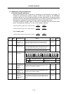
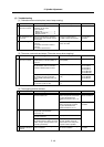
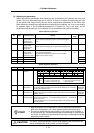
(5) Troubleshooting
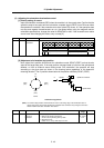
[1] Orientation does not take place (motor keeps rotating)
Cause Investigation item Remedy Remarks
1 Parameter setting
values are incorrect
The orientation detector and
parameter do not match.
SP037 (SFNC5)
Motor PLG.............................. 4
Spindle end detector .............. 1
Magnetic sensor..................... 2
Correctly set SP037 (SFNC5).
2 The specification are
not correct
Motor PLG orientation is attempted
with standard motor instead of motor
with Z phase.
Change to a motor having a
PLG-built-in motor with Z phase.
For motor PLG
orientation
3 Incorrect wiring The connector pin numbers are
incorrect,
The inserted connector number is
incorrect.
The cable is disconnected.
Correct the wiring.
Replace the cable.
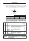
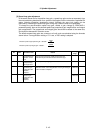
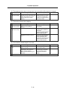
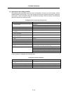
[2] The motor overtravels and stops. (The motor sways when stopping.)
Cause Investigation item Remedy Remarks
1 Parameter setting
values are incorrect
The gear ratio parameters:
SP025 (GRA1) to SP032 (GRB4) are
incorrect.
Correctly set SP025 (GRA1) to
SP032 (GRB4).
The phenomenon is improved when
the deceleration rate for orientation
parameter SP006 (CSP) is halved.
Readjust SP006 (CSP) This also applies to:
SP107 (CSP2)
SP108 (CSP3)
SP109 (CSP4)
SP121 (MPCSH)
SP122 (MPCSL)
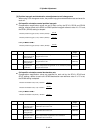
The phenomenon is improved when
the position loop gain parameters
SP001 (PGM) and SP002 (PGE) are
halved.
Readjust SP001 (PGM), SP002
(PGE).
This also applies to:
SP119 (MPGH)
SP120 (MPGL)
The orientation stop direction is set to
one direction (CCW or CW).
Set the SP097 (SPECO) /bit 0, 1
to "0".
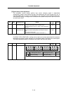
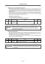
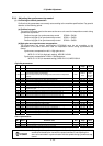
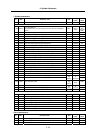
[3] The stopping position deviates.
Cause Investigation item Remedy Remarks
1 Mechanical cause The stopping position is not deviated
with the encoder axis.
There is backlash or slipping, etc.,
between the spindle and encoder.
The gear ratio between the
spindle and encoder is not 1:1 or
1:2.
For spindle end
detector orientation
There is backlash or slipping
between the spindle and motor.
The gear ratio between the
spindle and motor is not 1:1.
For motor PLG
orientation
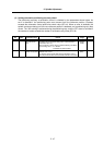
2 Noise The position detector's cable is
relayed with a terminal block
(connector), etc.
Do not relay the cable.
The position detector cable's shield is
not treated properly.
Properly treat the shield.
The peeled section of signal wire at
the position detector cable's connector
section is large. (A large section is not
covered by the shield.)
Keep the peeled section to 3cm or
less when possible. Keep the
peeled section as far away from
the power cable as possible.
3 The magnetic sensor
installation direction is
incorrect
Check the relation of the magnet and
sensor installation.
Correct the relation of the magnet
and sensor installation.
For magnetic sensor
orientation.